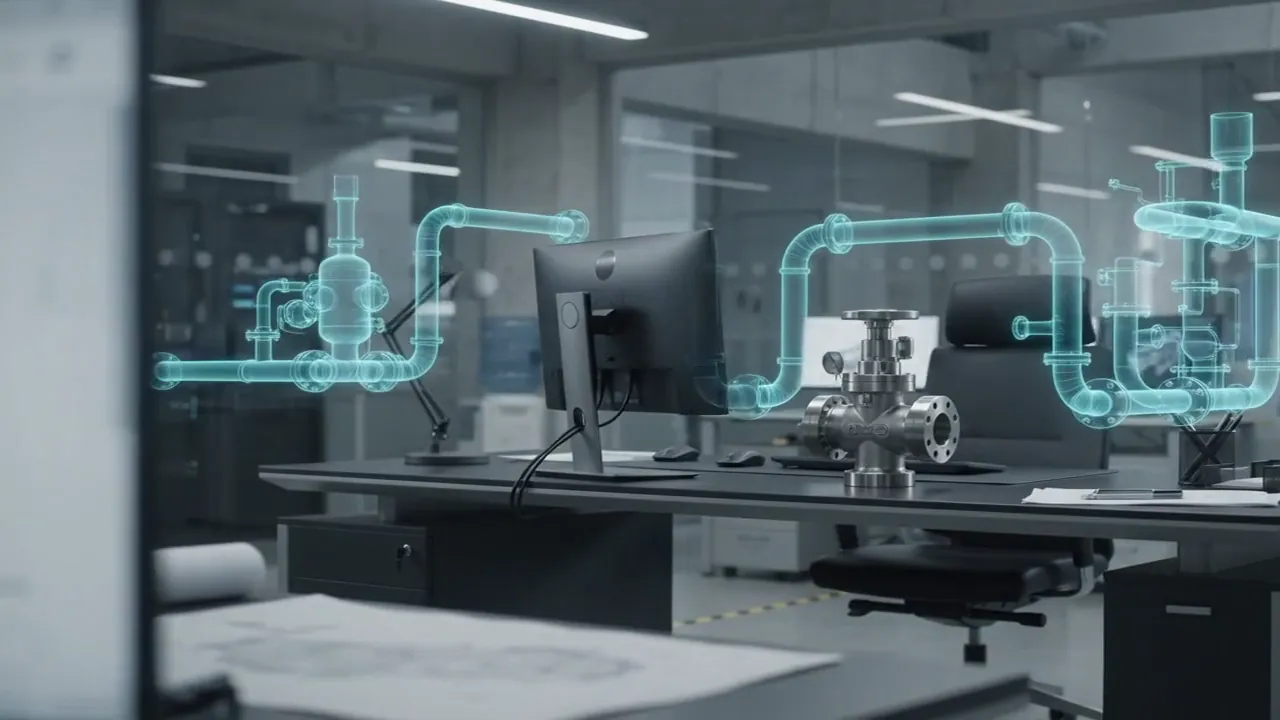
Transient ANSYS Fluent CFD of a 4-outlet grease distribution network. The study quantified a 578,850 Pa system pressure drop and caught a zero-delivery design flaw before fabrication.
Due to client NDA commitments, the showcased projects represent only a portion of our work and not the full scope of what we've delivered.
CFD Feasibility Study: Grease Distribution Piping Network for Bearing Lubrication
A bearing lubrication system required a branched piping network to deliver grease from a supply pump and tank to four bearing outlets. Before committing to fabrication, the client needed to verify whether the proposed pipe geometry and pump conditions could actually deliver grease to all four bearings. Fluxiss answered that question with a transient internal-flow CFD study in ANSYS Fluent 2024 R1.
The Challenge: A Highly Viscous Fluid in a Branched Network
Grease is not a forgiving fluid. At a viscosity of 100 Pa·s and a density of 900 kg/m³, it behaves nothing like water in a pipe network, and rule-of-thumb hydraulic sizing simply does not apply. The only reliable way to confirm delivery at every outlet was a full transient simulation of the real geometry.
Our Approach: Transient CFD from the Real CAD Geometry
- Internal fluid domain extracted directly from the client's SolidWorks pipe model
- Grease modelled as a highly viscous Newtonian fluid (100 Pa·s, 900 kg/m³)
- Time-dependent inlet flow schedule applied from 10s to 60s, decreasing from 3.73 to 0.621 cm³/s
- Outlet pressures and mass flow rates monitored at all four bearing outlets throughout the transient
Key Findings: A Design Flaw Found Before Fabrication
- Total system pressure drop: 578,850 Pa
- Outlet mass flow at all four bearings: 0 kg/s, no grease delivery
- Outlet pressures ranged from -577,000 to -578,000 Pa, a large negative pressure differential
- Root cause identified: pipe network resistance far exceeds the pump supply pressure for 100 Pa·s grease
Fluxiss reported the findings with clear corrective options: increase pump supply pressure, reduce the pipe length-to-diameter ratio, or redesign the manifold geometry. The client received a quantified, defensible basis for redesign before a single pipe was fabricated, exactly what a CFD feasibility study is for.