Computer Aided Engineering (CAE)
FEA, CFD, CAD and CAM under one roof - simulation-led design, drafting and manufacturing support for complex components, from concept model to machined part.
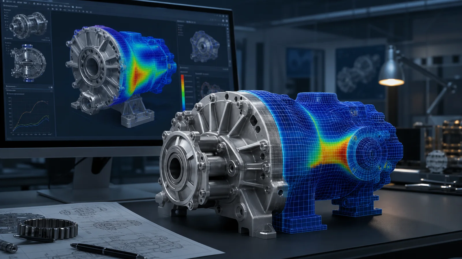
Computer Aided Engineering (CAE) gives product teams and asset owners a practical way to test performance before committing to tooling, fabrication, construction, or field modifications. Fluxiss brings finite element analysis, computational fluid dynamics, CAD, and CAM into one connected workflow, so every model answers a defined engineering question and every result can be traced into a design decision.
Our engineers work from concept geometry, legacy drawings, scan data, or an existing production model. We define the operating envelope, build the right level of simulation fidelity, check the result against applicable codes and test evidence, and return recommendations that a designer, fabricator, or project manager can act on.
Simulation-Led Engineering From Concept to Confident Decision
A useful CAE study starts with the decision—not the software. The question may be whether a bracket survives a new load case, whether a heat exchanger meets its duty, whether an enclosure keeps electronics below their temperature limit, or whether a component can be made lighter without losing fatigue life. We translate that question into measurable acceptance criteria before building the model.
The analysis plan then defines geometry assumptions, material models, boundary conditions, load combinations, interfaces, and the outputs that will control the decision. This keeps the simulation proportionate to the risk: efficient for early design screening and progressively more detailed as the design approaches certification or manufacture.
- Concept comparison and design trade-off studies.
- Failure investigation and root-cause simulation.
- Design optimization for mass, stiffness, flow, temperature, or life.
- Code compliance and independent design verification.
Finite Element Analysis for Strength, Stiffness and Life
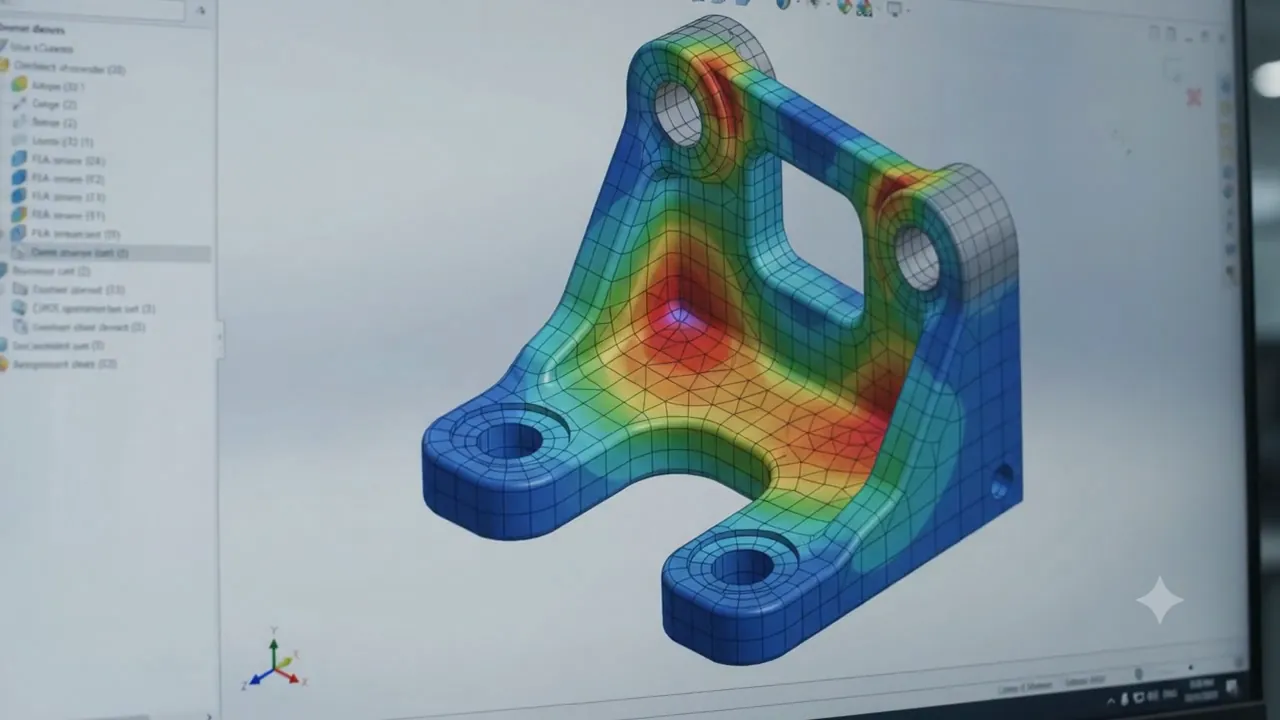
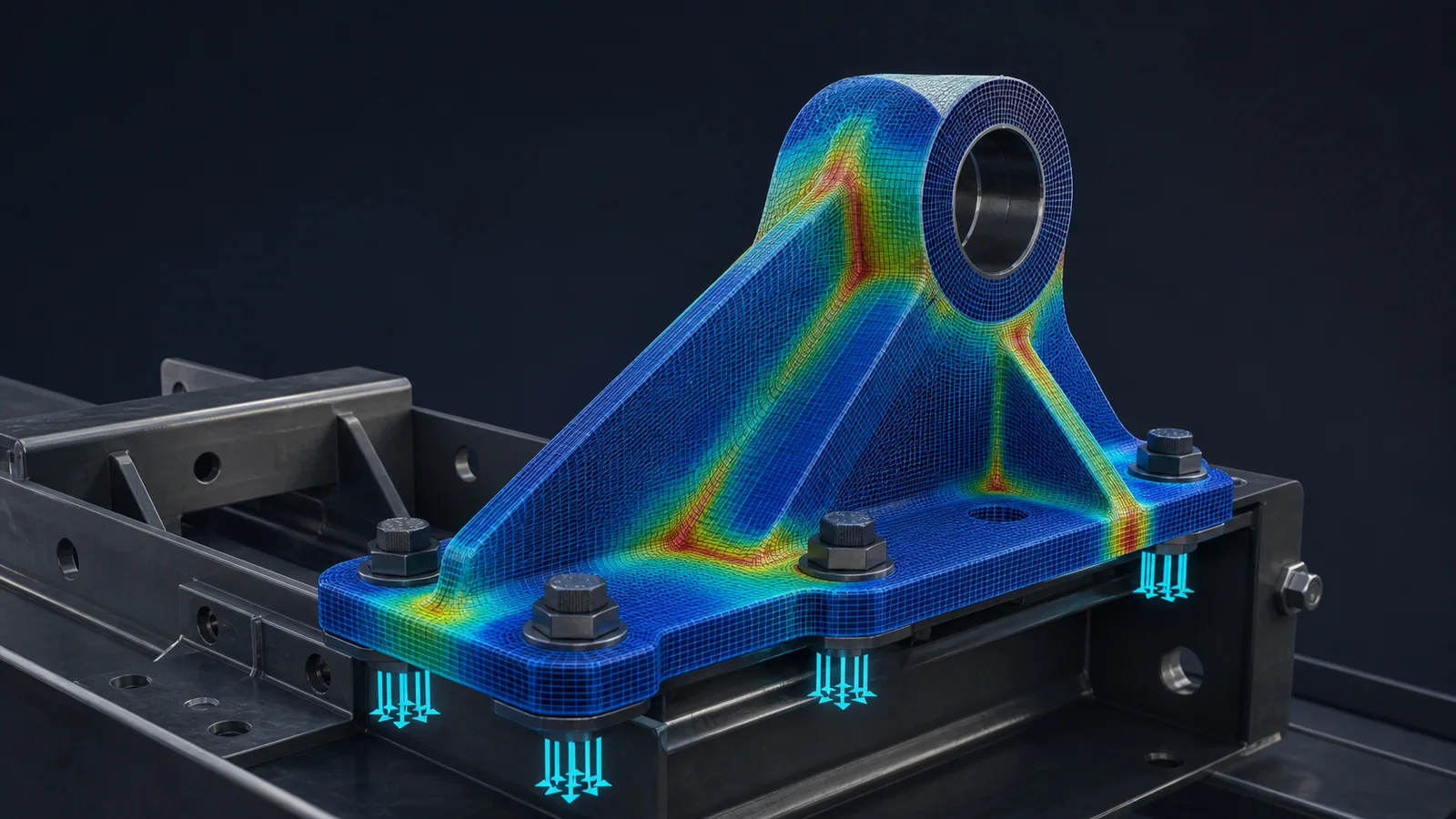
Our finite element analysis services evaluate how components and assemblies respond to real loads. Depending on the physics, that can include linear or nonlinear material behavior, contact, large deformation, thermal expansion, vibration, buckling, impact, and fatigue. The objective is not a colorful contour plot; it is a defensible margin against an agreed limit.
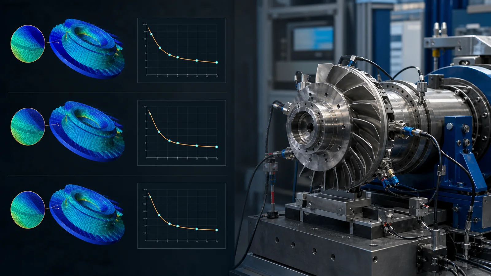
We use global models to capture the load path and refined local models where stress gradients, weld details, bolted joints, or geometric discontinuities control performance. Critical results are checked for mesh convergence, sensitivity to boundary assumptions, reaction-force balance, and consistency with hand calculations or established benchmarks.
- Static, nonlinear, modal, harmonic, transient, and response-spectrum analysis.
- Thermal stress, fatigue life, buckling, contact, and fracture-critical assessments.
- Equipment supports, pressure components, machinery, structures, and manufactured parts.
Computational Fluid Dynamics for Flow and Thermal Performance
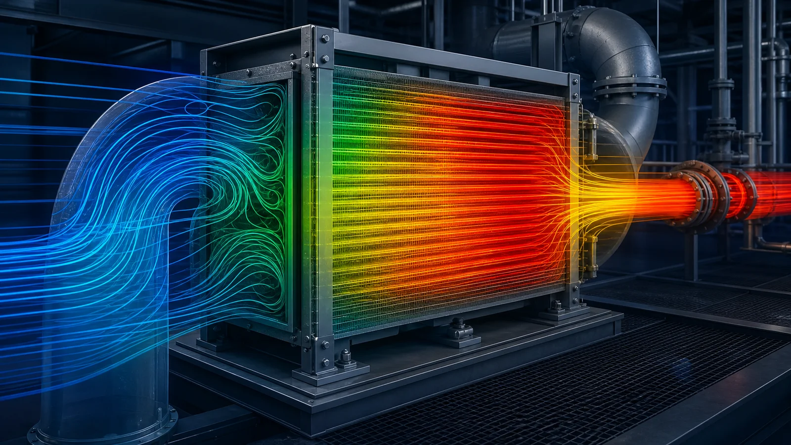
CFD makes invisible flow behavior measurable. Fluxiss uses computational fluid dynamics to predict velocity, pressure loss, temperature, species concentration, turbulence, and heat transfer before equipment or facilities are built. The analysis can expose recirculation zones, hot spots, short-circuiting, excessive pressure drop, poor mixing, or unsafe dispersion paths that are difficult to diagnose from drawings alone.
Our CFD work covers internal and external aerodynamics, HVAC and data-center airflow, electronics and battery thermal management, process mixing, exhaust dispersion, conjugate heat transfer, and multiphase applications. We document domain extent, mesh strategy, turbulence treatment, boundary conditions, convergence behavior, and result sensitivity so the study can be reviewed and reproduced.
- Pressure-drop reduction and flow-distribution optimization.
- Cooling-system sizing and thermal hot-spot mitigation.
- Ventilation effectiveness, comfort, smoke, and contaminant studies.
One Digital Thread From CAD to CAM
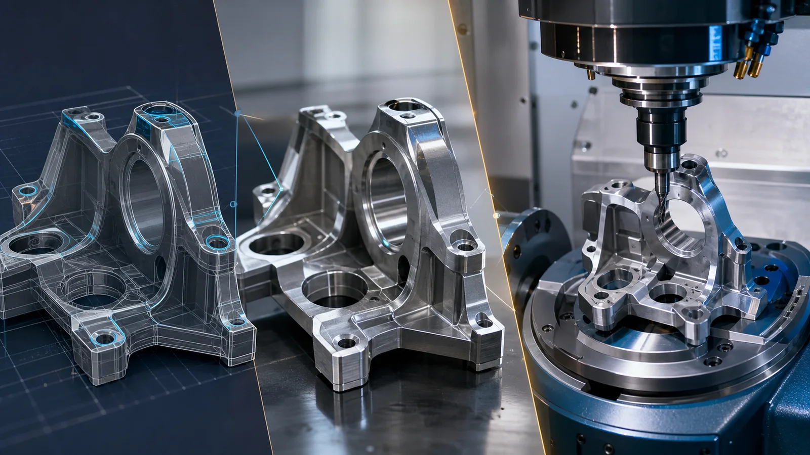
Analysis creates more value when its recommendations flow directly into the design. Our CAD team develops parametric parts and assemblies, manufacturing drawings, tolerances, bills of material, and configuration-controlled revisions. Simulation feedback is applied to the same design basis, reducing the handoff errors that occur when analysis and drafting are separated.
For production scopes, Fluxiss can extend the workflow into CAM with toolpath planning, fixture concepts, post-processing inputs, and setup documentation for three-axis through five-axis machining. Reverse-engineered scan or inspection data can also be rebuilt as clean, editable geometry before verification and manufacture.
- 3D parametric models and production-ready assemblies.
- GD&T drawings to ASME Y14.5 or ISO GPS requirements.
- CNC programs, setup sheets, tooling strategy, and fixture design support.
Verification and Validation That Makes Results Defensible
Simulation confidence comes from evidence. We separate verification—solving the equations correctly—from validation—showing that the model represents the real system well enough for its intended use. Model checks, mesh convergence, conservation balances, sensitivity studies, benchmark cases, and comparison with test or operating data are selected according to the consequence of the decision.
Every critical result is reviewed by an engineer who was not responsible for the original setup. Assumptions and limitations are stated clearly, and the report identifies which conclusions are robust, which depend on uncertain inputs, and what additional data would reduce uncertainty. This gives clients a record that can support design reviews, third-party checks, certification discussions, and future revisions.
Industries and Engineering Problems We Support
Fluxiss applies CAE across energy, oil and gas, process plants, buildings, marine and offshore systems, automotive products, renewable energy, industrial machinery, electronics, and advanced manufacturing. The same disciplined workflow scales from a single component to a coupled system involving structures, heat transfer, fluid flow, vibration, and manufacturing constraints.
- Industrial equipment, piping components, skids, vessels, and support systems.
- Automotive structures, crashworthiness, aerodynamics, NVH, and thermal systems.
- Marine structures, offshore equipment, hydrodynamic loads, and machinery foundations.
- Renewable-energy equipment, battery systems, solar structures, and wind components.
What You Receive From Fluxiss
Deliverables are tailored to the project stage and may include the analysis plan, model files, input register, assumptions, convergence evidence, code checks, contour and history results, design recommendations, revised CAD, manufacturing drawings, and a concise executive summary. Native files and a clear revision record can be included so your team is not locked into a presentation-only result.
Send us your geometry, operating conditions, materials, load cases, acceptance criteria, and the decision deadline. We will define a right-sized CAE scope and explain what information is still needed before analysis begins. Discuss Your CAE Project
Scope of Work
Each item below is a concrete workstream. Use it to decide what you need in scope before requesting a quote.
Specialised Computer Aided Engineering (CAE) scopes.
Each scope below has its own dedicated page with full details.
Engineered to the codes that govern your project.
How this engagement runs.
A simple, reviewable workflow so the client always knows where the project stands.
Inputs
Gather drawings, specs and codes.
Model
Build the analytical or 3D model.
Analyze
Run load cases against code allowables.
Review
Internal QC and client markups resolved.
Deliver
Issue construction package + RFI support.
What you receive.
The output is packaged for review, fabrication, construction or internal approval.
Questions, answered.
Most projects need them together - one simulation-led team takes your component from concept CAD through analysis to manufacturable drawings and CNC programs without hand-offs.
Engineering guides for your next decision
Manufacturing & DFM · 3 min read
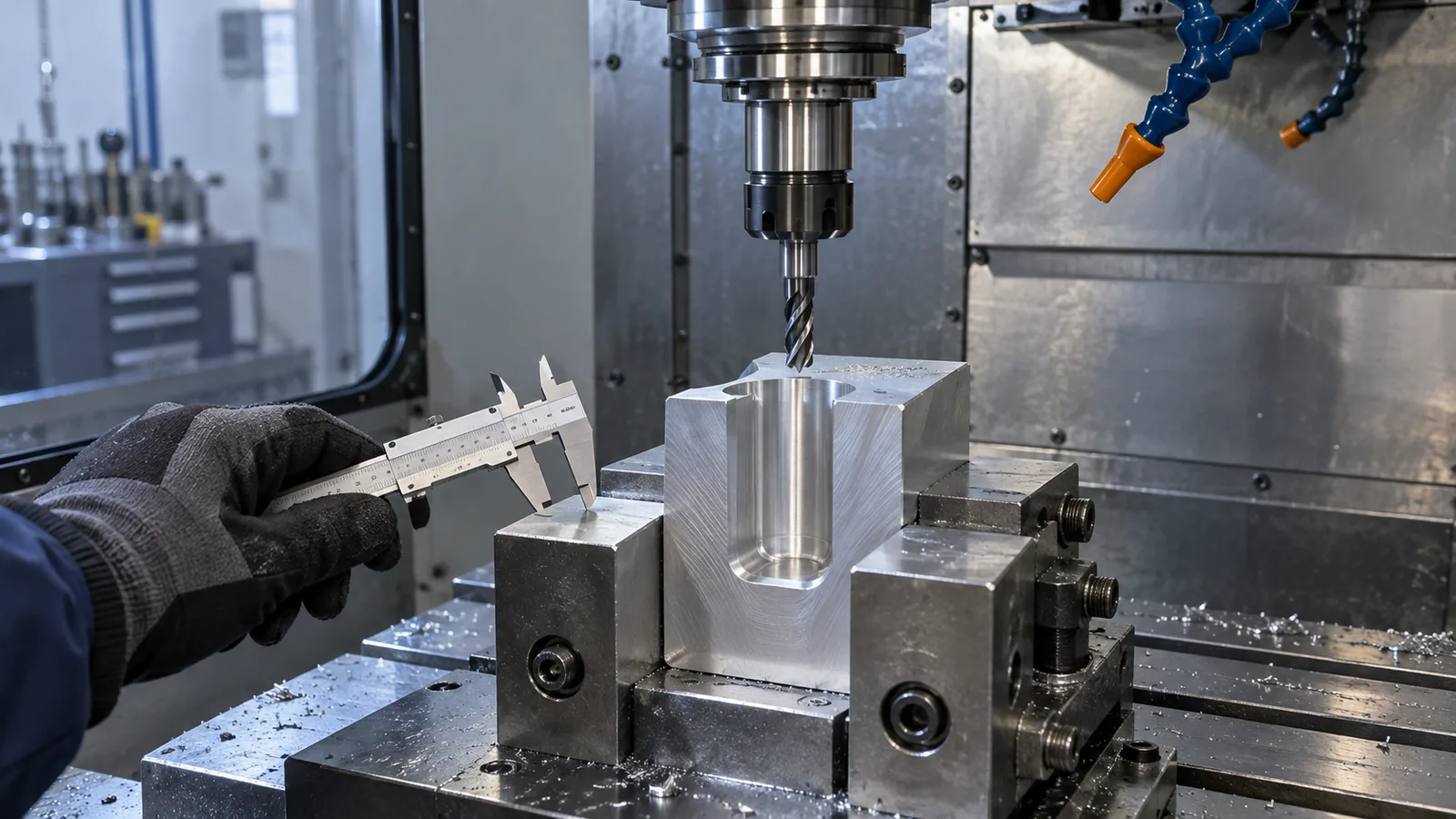
Why Your CAD Design Is Difficult to Manufacture: Common DFM Problems
Find manufacturability problems in tool access, wall stiffness, datums, tolerance choices and inspection before releasing CAD for production.
Read article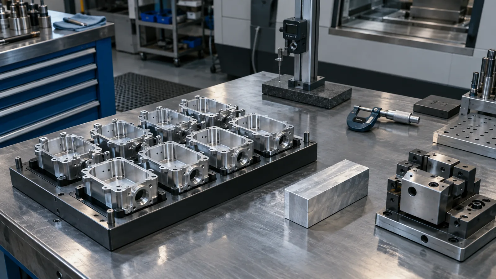
Manufacturing & DFM · 4 min read
Design for Manufacturing: 10 Engineering Mistakes That Increase Production Cost
Ten DFM cost drivers to review, from process selection and excess setups to tolerance allocation, inspection access and uncontrolled revisions.
Read article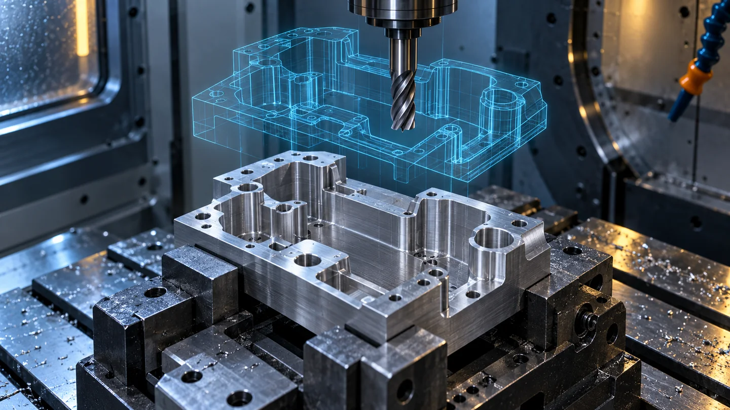
Manufacturing & DFM · 7 min read
From CAD to CNC: Common Problems That Delay Manufacturing
From CAD to CNC: Common Problems That Delay Manufacturing. A practical Fluxiss guide to inputs, analysis workflow, review checks and engineering deliverables.
Read articleLet's Build Something Great Together.
Partner with Fluxiss for engineering that holds up - under pressure, under load, under scrutiny.