
Piping is usually the largest single discipline on a process plant, and it is also where small design gaps turn into expensive site rework. A missing vent, a support that clashes with a cable tray or a material take-off that undercounts flanges can each hold up construction for days. Most of these problems are not engineering mistakes in isolation; they come from deliverables that were produced without a clear link to the ones before and after them.
This guide follows a line from its first appearance on a P&ID to the isometric a pipe fitter uses on site. At each step it explains what the deliverable contains, what it needs as input and what goes wrong when that hand-off is weak.
Step 1: The P&ID Sets the Rules
The piping and instrumentation diagram (P&ID) defines what the system is: every line, valve, instrument, line number, size, specification class and control loop. It is not drawn to scale, but every later piping deliverable inherits its data. If a line class or design condition is wrong on the P&ID, it will be wrong in the model, the stress calculation and the MTO.
Good practice is to issue the P&ID with a line list that records design pressure, design temperature, fluid service and insulation for each line. That line list becomes the input sheet for stress analysis and material selection. For a deeper look at how P&IDs are read and used, see our guide on what a P&ID is and how it is used in process engineering.
Step 2: 3D Piping Layout Turns Logic Into Space
Piping layout design routes each line through the plant in three dimensions: equipment nozzle orientation, pipe rack levels, access for operation and maintenance, valve handwheel heights, drainage slopes and safe distances from hot surfaces. Layout decisions made here decide how flexible the system will be and how easy it is to support.
The model is built with parametric components so that a change to a nozzle or a rack elevation updates connected geometry instead of leaving broken ends. This is also the point where the piping model must be checked against structural, electrical and HVAC models, because a clash found in the model costs minutes while the same clash found on site costs a cut and re-weld.
Step 3: Stress Analysis Checks the Layout Can Survive
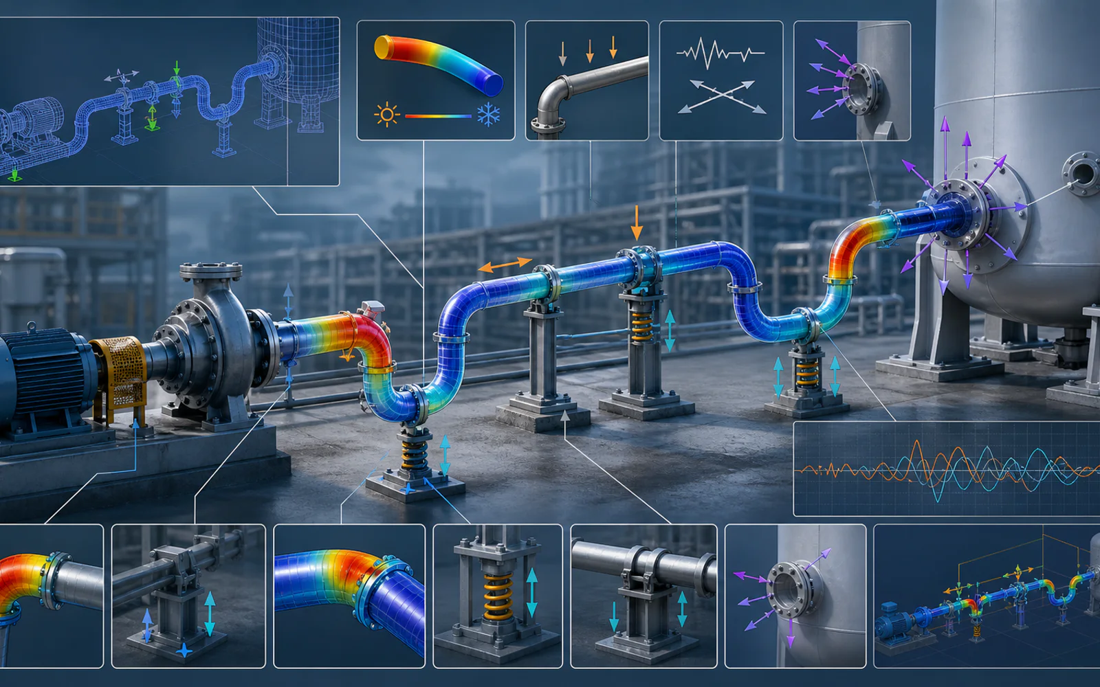
Once routing is stable, critical lines go to pipe stress analysis. Lines are normally selected using a criticality list: high temperature, large diameter, lines connected to rotating equipment, relief lines and lines subject to seismic or wind loads. The analysis checks sustained, thermal expansion and occasional load cases against the governing code, typically ASME B31.3 for process piping, and confirms that nozzle loads stay inside equipment allowables.
Stress results often send the layout back a step: an extra loop, a relocated anchor or a change from a rigid support to a spring. That loop is normal and is the reason stress work should start before isometrics are frozen, not after. If you are new to the subject, our complete guide to pipe stress analysis covers load cases and software choices in more detail.
Step 4: Supports Are Designed, Not Just Placed
Every support in the stress model has a function: rest, guide, line stop, anchor, spring or snubber. Support design converts those functions into real steel, with loads taken from the stress output and checked against the structure that carries them. Support loads also go to the structural team so pipe racks and platforms are designed for the actual piping reactions.
Step 5: Isometrics Are the Construction Document
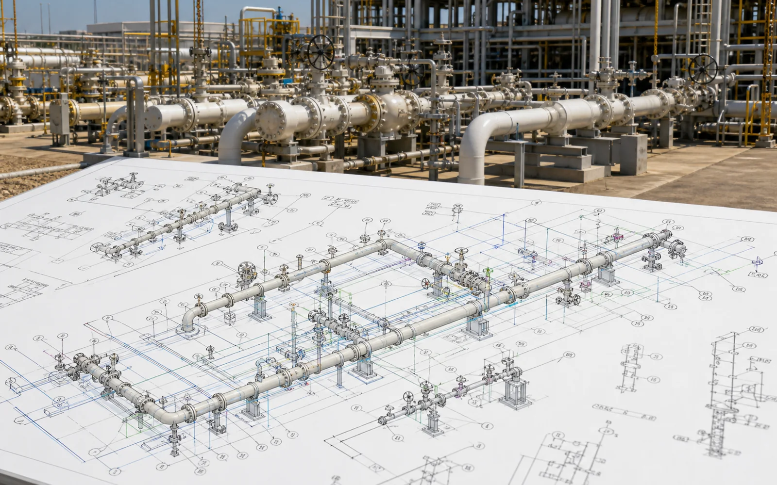
An isometric drawing shows one line, or part of one, with every dimension, fitting, weld, support tag and bill of materials needed to fabricate and install it. Isometrics are extracted from the 3D model, so their accuracy depends on the model being complete and on stress and support changes having been fed back first.
Common isometric problems are missing continuation references, support tags that do not match the support schedule and weld numbers that are not unique. Each one slows down fabrication or quality records. Our project notes on piping isometric drawings for crude receiving facilities show how these checks are handled on a live refinery scope.
Step 6: Material Take-Offs Close the Loop With Procurement
The material take-off (MTO) totals pipe lengths, fittings, flanges, gaskets, bolts, valves and supports from the model and isometrics. Early MTOs are used to order long-lead items such as alloy pipe and large valves; later MTOs are reconciled against isometrics so that the site does not run short. A surplus allowance is usually applied by item type, and that allowance should be stated rather than hidden inside the quantities.
Where the Chain Usually Breaks
- P&ID revisions that are not pushed into the line list and model.
- Isometrics issued before stress analysis on critical lines is complete.
- Support changes from stress analysis that never reach the support schedule or the MTO.
- No multidiscipline clash review before isometric extraction.
- Existing plant tie-ins designed from old drawings instead of verified as-built data.
The last point matters on brownfield work. Where drawings are out of date, a site survey or laser scan followed by as-built P&ID and layout updates is the safest starting point, as covered in our article on as-built P&ID and piping layout services.
How Fluxiss Supports the Full Piping Chain
Fluxiss engineers deliver P&ID development, 3D piping layout, stress analysis, support design, isometrics and MTOs as one connected scope, or as individual packages that plug into a client or EPC contractor's workflow. If you are planning a new unit or a brownfield modification, schedule a meeting with our piping team to agree the deliverable list and hand-off points before design starts.
Frequently Asked Questions
Before isometrics are issued for construction. Stress results often change routing and supports, so isometrics extracted too early have to be revised.
Practical engineering explainers connecting analysis methods, design inputs and project decisions.
Related articles.

Let's Build Something Great Together.
Partner with Fluxiss for engineering that holds up - under pressure, under load, under scrutiny.