Pressure Vessel Design from Design Basis to Hydrotest: Calculations, Nozzle Loads, FEA and Code Compliance
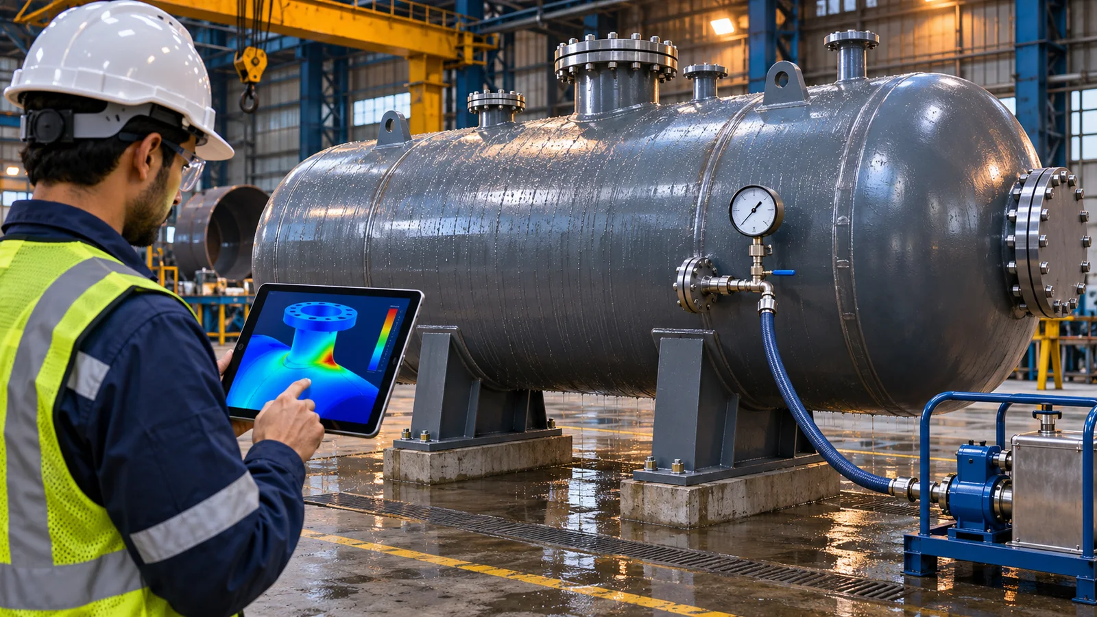
Most pressure vessel problems are found late: a nozzle that fails a third-party check, a shell that is too thin once corrosion allowance is added, a saddle that overstresses the shell, or a calculation package the inspector will not accept. Each of these is cheaper to fix at the design stage than in the fabrication shop.
This guide follows a vessel through the engineering steps in the order they should happen and shows where each step feeds the next.
Step 1: Fix the Design Basis
Every calculation depends on the design basis, so it has to be agreed first: design pressure and temperature, minimum design metal temperature, fluid and corrosion rate, corrosion allowance, material, joint efficiency and radiography, external loads such as wind and seismic, and the governing code. Most vessels are designed to ASME Section VIII Division 1; Division 2 or EN 13445 may suit thicker or high-duty vessels, and atmospheric storage tanks follow API 650. Our article on ASME Section VIII Div 1 vs Div 2 explains how to choose.
- Design pressure and temperature, including vacuum or external pressure cases.
- Corrosion allowance based on the actual fluid and design life.
- Material specification and impact test requirements at the minimum design metal temperature.
- Nozzle schedule with sizes, ratings and the loads the piping will apply.
Step 2: Shell, Head and MAWP Calculations
With the basis fixed, the shell and heads are sized for internal pressure, then checked for external pressure, hydrostatic head and combined loads. The maximum allowable working pressure follows from the final thicknesses. Our design and calculation service produces this package in PV Elite or COMPRESS, and our guides on how to calculate MAWP and why corrosion allowance matters in thickness calculations show the method.
Vessels under vacuum or external pressure need stiffening rings or a thicker shell, and the buckling check often governs. Our article on how external pressure causes buckling explains why.
Step 3: Nozzles, Reinforcement and Piping Loads
Every opening weakens the shell, so each nozzle is checked for area replacement or reinforcement. Then come the external loads from connected piping. Local stresses at the nozzle are checked with WRC 107 or WRC 537 using loads taken from the pipe stress analysis, which is why the vessel and piping teams must share the same nozzle schedule. Our guide to nozzle reinforcement problems lists the issues we see most often.
Step 4: Supports, Wind and Seismic
Horizontal vessels sit on saddles, vertical vessels on skirts or legs. Each support type introduces local stresses into the shell that must be checked together with wind, seismic and operating weight. Our comparison of skirt, saddle and leg supports covers the choice, and the base and anchor design is handed to our structural engineering team so the foundation matches the vessel loads.
Step 5: FEA Where the Code Runs Out
Closed-form code rules cover standard shapes. Large nozzles close to each other, non-standard heads, heavy external loads, cyclic duty and local thermal gradients go beyond them. In those cases a finite element analysis to ASME Section VIII Division 2 Part 5 classifies the stresses and checks them against the code limits, including fatigue where cycles matter. Our articles on when to use FEA for pressure vessel design and on pressure vessel fatigue analysis explain the triggers.
Step 6: Compliance, Review and Hydrotest
The final package collects the calculations, the FEA report where applicable, the general arrangement drawing and the material summary so the authorised inspector or third-party reviewer can check them. The hydrotest pressure is calculated from the code and the vessel is checked for the test condition, including the weight of water on the supports. Our safety and compliance service prepares this package, and our article on why calculations fail third-party review shows what reviewers reject.
How Fluxiss Helps
Fluxiss delivers the full chain under its pressure vessel design service, from design basis and code calculations to nozzle loads, FEA verification and the compliance package, typically in 7 to 14 business days. The pressure vessel topic hub collects all our related guides. To discuss a vessel, contact Fluxiss or schedule a technical meeting.
Frequently Asked Questions
Most vessels are designed to ASME Section VIII Division 1. Division 2 can save material on thick or high-duty vessels, EN 13445 is common in Europe, and atmospheric storage tanks follow API 650. The project specification or the local authority usually decides.
Practical engineering explainers connecting analysis methods, design inputs and project decisions.
Related articles.
Let's Build Something Great Together.
Partner with Fluxiss for engineering that holds up - under pressure, under load, under scrutiny.