Pipe Stress Analysis for Thermal Expansion: Common Problems and Solutions

A piping system can fit perfectly during installation and develop large reactions when it reaches operating temperature. Thermal growth is not itself a defect: the design problem is whether the routing and restraints accommodate that movement while supporting weight and protecting equipment. Pipe stress analysis connects the temperature envelope to displacement, stress range and interface loads.
Estimate free growth, then examine restraint
For a simple uniform-temperature illustration, free expansion is ΔL = αLΔT, using a suitable mean expansion coefficient over the temperature interval. A 30 m run with assumed α = 12 × 10⁻⁶/K and a 150 K rise would grow about 54 mm if unconstrained. Real systems need material expansion data and the actual temperature distribution.
That movement estimate is not a pipe-stress result. Bends, branches, restraints, friction and equipment movement determine how growth is accommodated. The fully restrained elastic estimate EαΔT is an idealised bound for a simple bar, not a substitute for code-based piping flexibility assessment.
Define credible operating and cycling cases
Collect installation temperature, normal operation, startup, shutdown, cleaning, standby and upset conditions. Different branches may heat at different times. A cold bypass connected to a hot main can create a restraint pattern that the single normal-temperature case misses.
Separate sustained load checks, operating reactions and displacement stress-range assessment. ASME identifies B31.3 as a process-piping standard; whether B31.3 or another piping code applies depends on the system and jurisdiction. Use the project-adopted rules and edition rather than applying one default across every plant.
Model the restraints that are actually installed
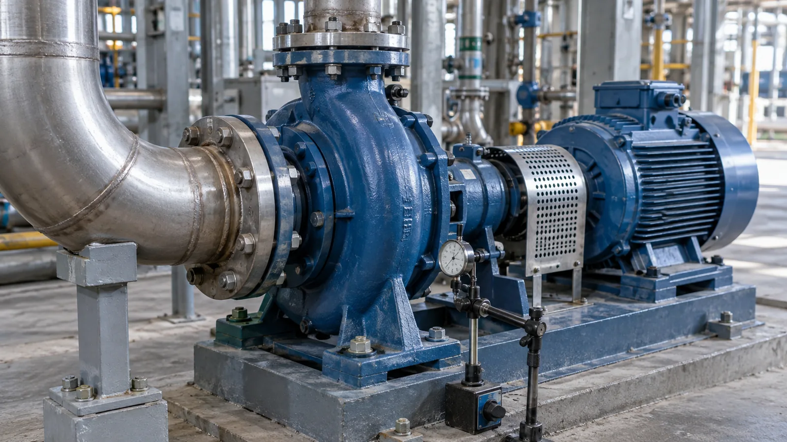
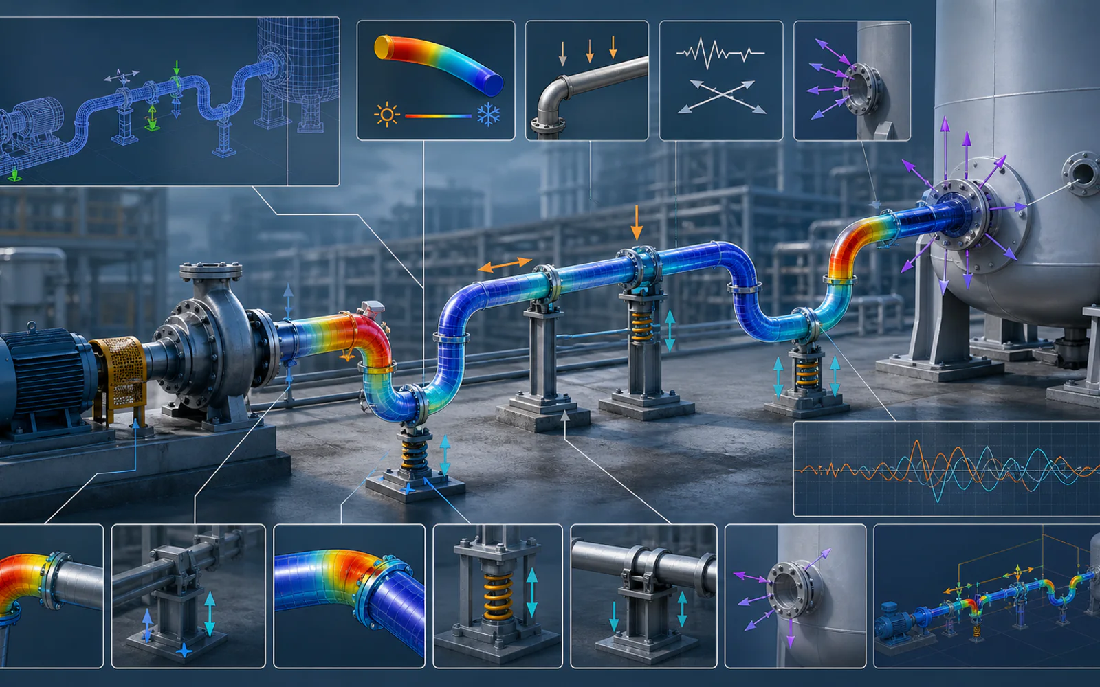
A sliding support carries weight but may also resist movement through friction. A guide limits selected directions; a line stop limits axial motion; an anchor provides a defined restraint that still has real stiffness. Record gaps, friction assumptions, spring properties and support elevation.
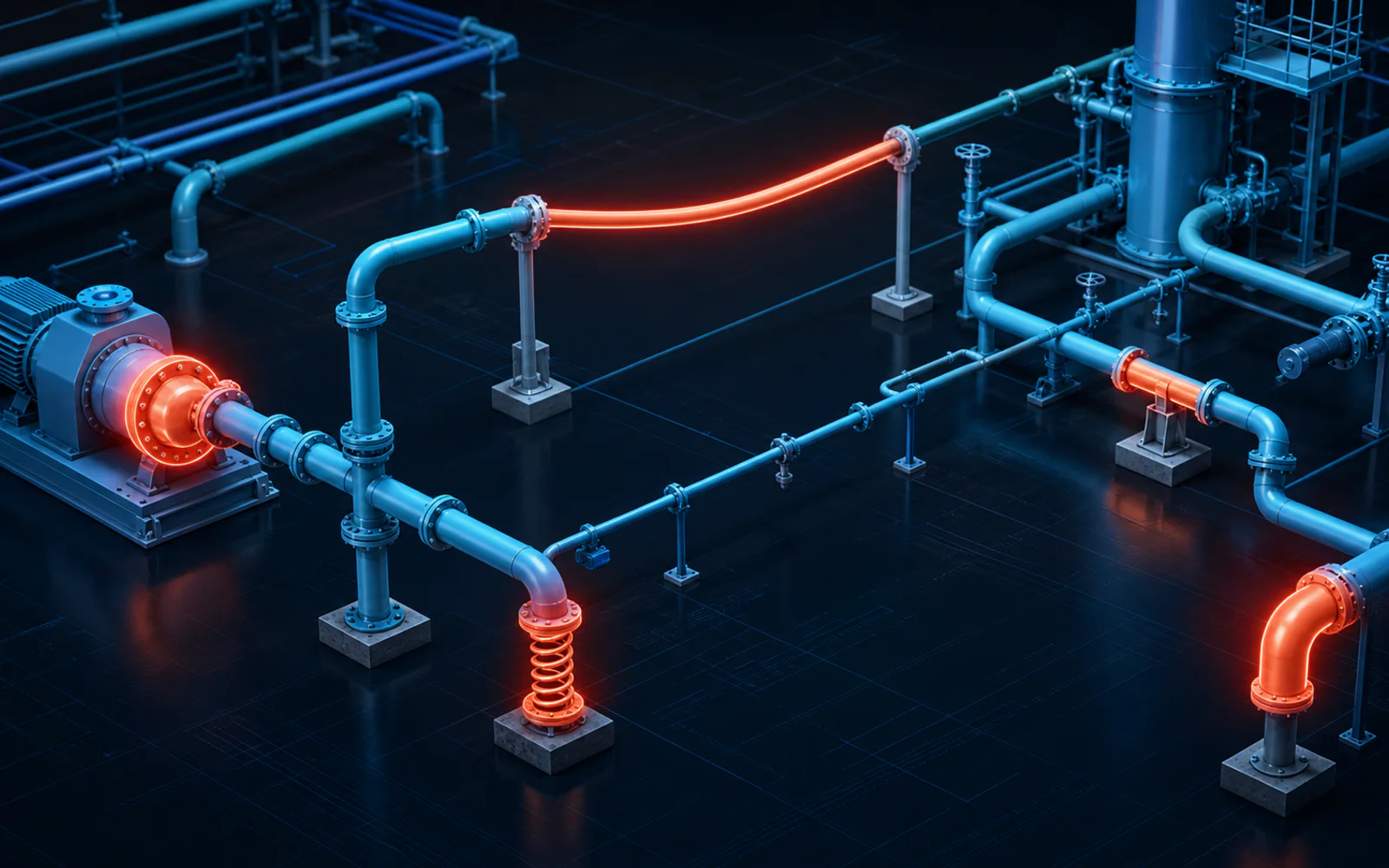
Inspect the intended hot and cold positions. A guide placed too close to an expanding elbow can generate large forces, while a missing support can increase equipment loads under weight. Support lift-off and friction make the path history-sensitive and may require nonlinear restraint treatment.
Solve the cause rather than adding anchors
Possible changes include routing flexibility, support relocation, revised guides, spring supports or an engineered expansion joint. Each option introduces tradeoffs. A loop needs space and support; a spring needs travel and load review; an expansion joint may require pressure-thrust restraint and stability checks.
Compare nozzle loads, support reactions, clearances and displacement ranges as well as the code stress result. Moving a peak out of one pipe segment is not a successful redesign if it overloads a pump or building connection.
Close the design against the as-built system
Issue support details, movement envelopes, spring settings and equipment load tables with the calculation. During commissioning, compare observed travel with the intended behaviour through an appropriate inspection procedure. Unexpected binding or displaced supports should trigger an engineering review.
For existing plants, provide marked-up isometrics, temperatures, support photographs and the history of leaks or vibration. Fluxiss can use these inputs to distinguish a flexibility problem from an installation, support or equipment-interface issue.
Frequently Asked Questions
No. Equipment nozzle loads and support reactions require their own checks against the applicable acceptance limits.
Technical references & further reading
Practical engineering explainers connecting analysis methods, design inputs and project decisions.
Related articles.
Let's Build Something Great Together.
Partner with Fluxiss for engineering that holds up - under pressure, under load, under scrutiny.