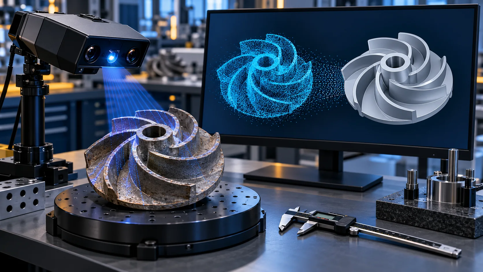
This service spotlight explains how the Fluxiss Reverse Engineering service converts an existing component or assembly into engineering information that can be reviewed, edited and manufactured. The starting point may be a legacy part with no drawing, an incomplete archive, a worn component that must be replaced or an installation that needs an accurate as-built model. The goal is not simply to copy the visible surface. It is to establish the geometry, interfaces, tolerances and likely design intent well enough for the client to make a controlled repair, redesign or production decision.
The workflow begins by defining the required output and the condition of the source part. Simple prismatic features may be captured with calibrated manual metrology, while complex cast, formed or freeform geometry may need structured-light or laser scanning. The resulting point cloud or polygon mesh is cleaned and aligned to agreed datums before any solid model is created. Reference dimensions, mating parts and assembly constraints are recorded separately so that scan noise and service wear are not mistaken for intentional design features.
“See how Fluxiss turns legacy parts, incomplete drawings and physical assemblies into validated CAD models, manufacturing drawings and redesign inputs through a controlled reverse-engineering workflow.”
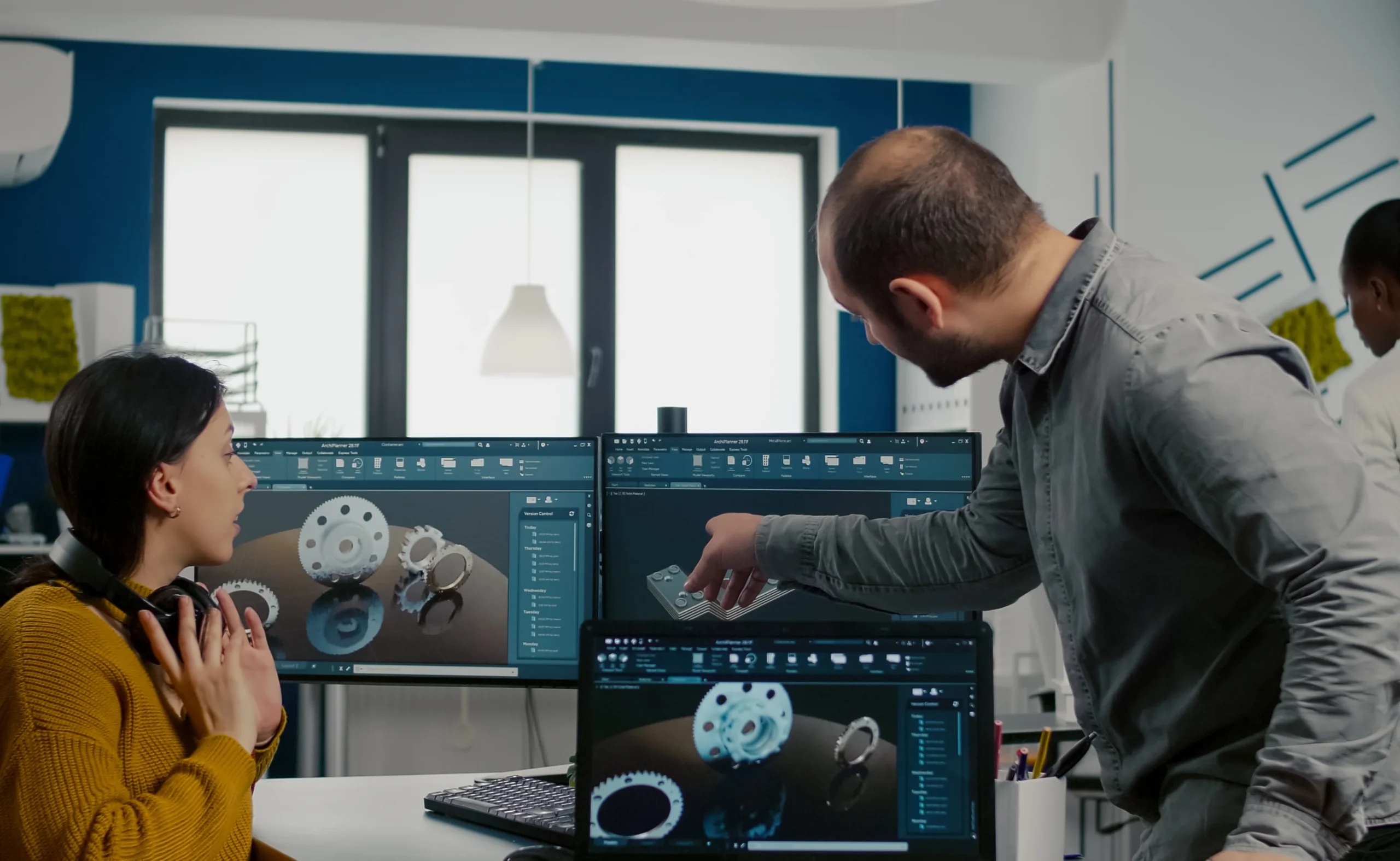
Computer Aided Design turns that evidence into a usable model. Through 3D Parametric Modeling, cylinders, planes, hole patterns, fillets and other design features are rebuilt as editable geometry rather than delivered as an unstructured surface. Where a part has worn unevenly, the reconstructed model separates measured as-is condition from the nominal geometry proposed for replacement. The client can review both states and agree which dimensions come from inspection, which come from a mating interface and which remain assumptions requiring confirmation.
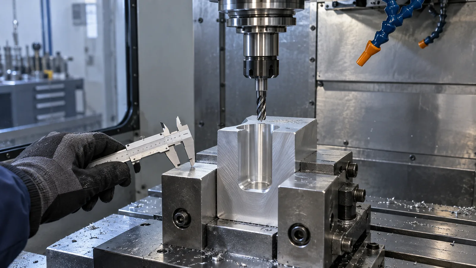
Validation is the step that makes the model defensible. Critical dimensions are checked back against the physical part, scan deviation is reviewed across the surfaces that matter and fit is tested against neighbouring components or an assembly model. If the replacement changes material, wall thickness, load path or operating duty, Finite Element Analysis can be scoped to assess the revised design rather than assuming the historical part remains suitable. This is also where the team documents exclusions, inaccessible surfaces and tolerances that cannot be recovered from a worn sample alone.
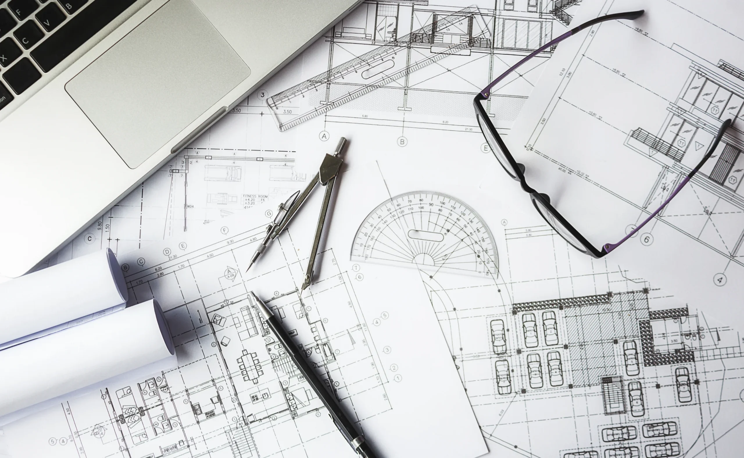
Once the geometry is approved, 2D Technical Drafting converts it into controlled manufacturing information: dimensions, datums, tolerances, material, finish and inspection requirements. Computer Aided Manufacturing can then use the approved model for toolpath planning, while the drawing remains the contractual definition of what must be made and checked. Our guides to what a parametric 3D model is, why CAD designs become difficult to manufacture and how engineering drawings are created and used provide additional context for teams preparing a replacement-part package.
A useful reverse-engineering enquiry includes clear photographs, the part and equipment description, available drawings or manuals, mating components, material information, operating conditions, known failure or wear history, required quantity and the intended output format. State whether the objective is an as-is digital record, a like-for-like replacement, a repair drawing or a redesigned part. Teams can contact Fluxiss with that information or schedule a technical meeting to agree the capture method, validation plan and deliverables before work begins.
Fluxiss Team contributes services insights to the Fluxiss content library.
Related articles.
Let's Build Something Great Together.
Partner with Fluxiss for engineering that holds up - under pressure, under load, under scrutiny.