From 3D CAD Model to Shop Floor: Parametric Modeling, Drafting, GD&T, CAM and Prototyping
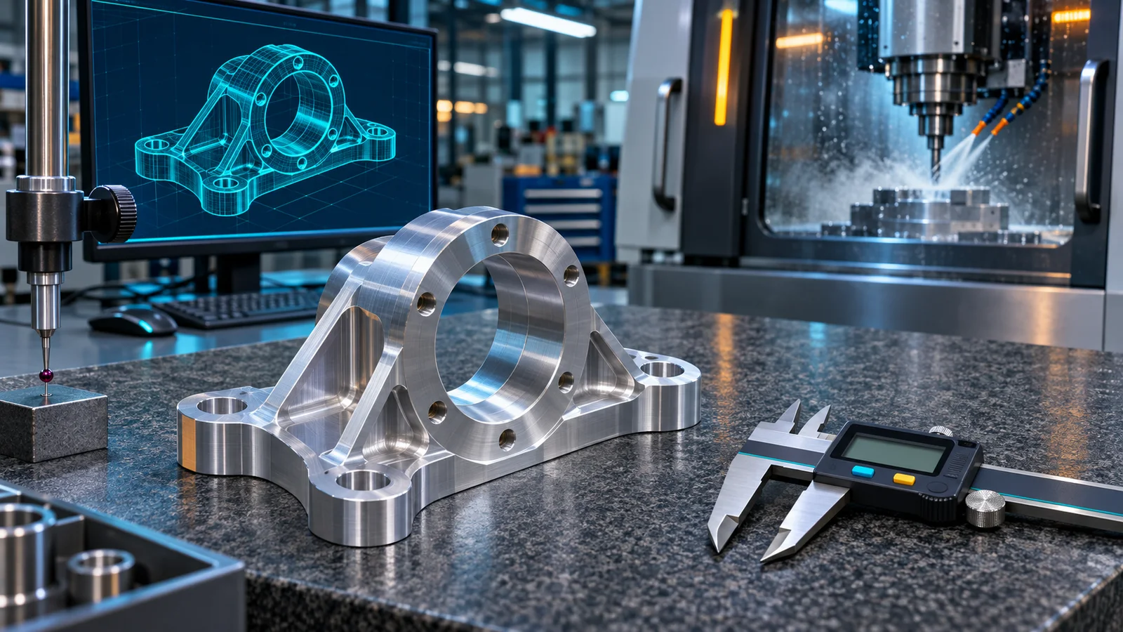
A CAD model can look finished on screen and still be impossible, or very expensive, to make. Holes are dimensioned from the wrong face, tolerances are tighter than any process can hold, or the drawing does not match the model. The fix is not better software. It is a clear chain from design intent to the shop floor, where each step checks the one before it.
This guide follows a mechanical part through that chain and links each step to the Fluxiss service that delivers it.
Step 1: Build the 3D Parametric Model Around Design Intent
A parametric model is driven by dimensions, constraints and relationships rather than fixed geometry. Done well, it captures design intent: change the bore diameter and the wall thickness, fillets and mounting holes follow. Done badly, one change breaks the feature tree. Our 3D parametric modeling service builds models with stable references, clear naming and configurations for product variants, so they stay editable for the life of the product.
- Sketch on datum planes and reference geometry, not on faces that may move.
- Name key dimensions and drive variants from a table or global parameters.
- Model to nominal size and let tolerances live on the drawing.
- Keep purchased parts and fasteners in a managed library.
If you are new to the terminology, our article on what computer-aided design and drafting is gives the background.
Step 2: Produce 2D Drawings with GD&T
The drawing is still the contract with the manufacturer. It carries the datums, tolerances, surface finish, material, heat treatment and inspection notes that a model alone does not. Geometric dimensioning and tolerancing (GD&T) to ASME Y14.5 or ISO GPS states how a feature may vary relative to the datums that matter in assembly, which is far clearer than a list of plus or minus values. Our 2D technical drafting service produces drawings directly from the model so the two never disagree.
Step 3: Check Design for Manufacture
Before release, the design is checked against the process that will make it: tool access, internal corner radii, wall thickness, draft angles for cast or moulded parts, standard hole sizes and tolerances the chosen machine can hold. Our article on why CAD designs are difficult to manufacture lists the problems we see most often. Where a part carries significant load or heat, a finite element analysis confirms the geometry before metal is cut.
Step 4: CAM and CNC Programming
Computer-aided manufacturing turns the model into toolpaths: stock definition, fixturing, tool selection, feeds and speeds, and post-processed G-code for a specific machine. Simulation catches collisions and gouges before they happen on the machine. Our computer-aided manufacturing and CNC programming services handle this stage, and our article on the difference between CAD and CAM explains how the two fit together.
Step 5: Prototype, Fixture and Tooling
A prototype proves fit and function before production tooling is paid for. Additive manufacturing is fast for form and fit checks; a machined prototype in the final material is better for functional and load tests. For series production, jigs and fixtures locate the part on the same datums used on the drawing, which keeps inspection results consistent. Our rapid prototyping and additive manufacturing and tooling and fixture design services cover this step.
Where Reverse Engineering Fits
Many projects start without a model at all: a worn spare part, a legacy component with no drawings, or a competitor benchmark. Reverse engineering uses 3D scanning and measurement to rebuild a clean parametric model, which then enters the same chain from Step 1. Our reverse engineering service and the matching news spotlight describe the process.
How Fluxiss Helps
Fluxiss provides the full chain under its computer-aided design service, from parametric modeling and GD&T drawings to CAM, prototyping and tooling, or supports your team on single stages. Our service spotlight on 3D parametric modeling and 2D technical drafting gives a short overview. To discuss a part or product, contact Fluxiss or schedule a technical meeting.
Frequently Asked Questions
Model to nominal size and state tolerances on the drawing or in model-based definition annotations. Modelling parts at a tolerance limit causes confusion in assemblies and CAM.
Practical engineering explainers connecting analysis methods, design inputs and project decisions.
Related articles.
Let's Build Something Great Together.
Partner with Fluxiss for engineering that holds up - under pressure, under load, under scrutiny.