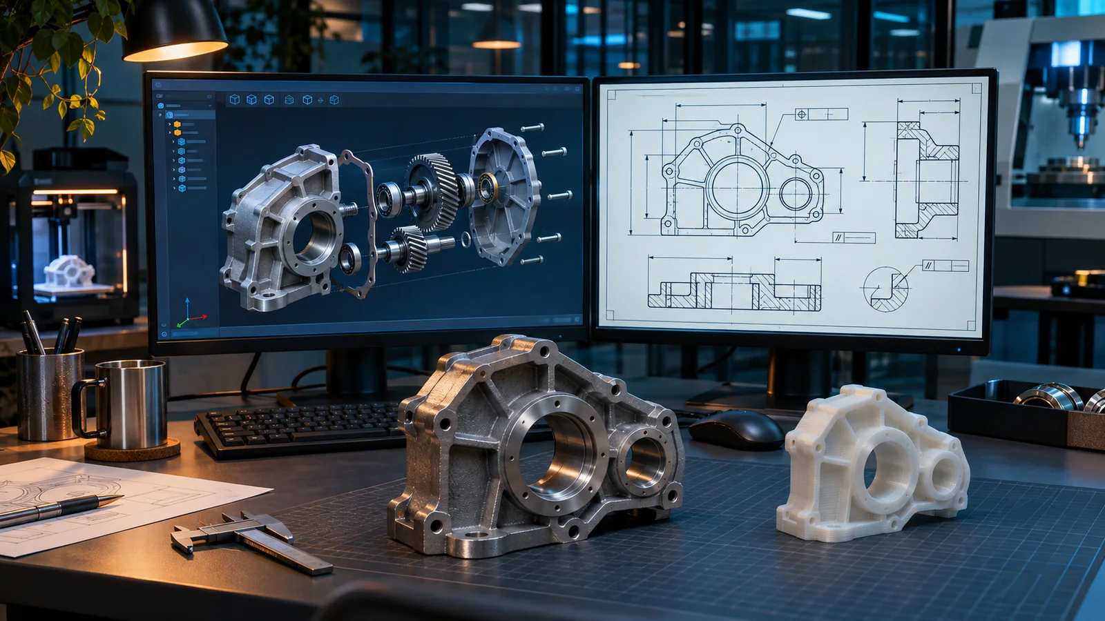
This service spotlight looks closely at the two core sub-services under Fluxiss Computer-Aided Design: 3D Parametric Modeling and 2D Technical Drafting. Our earlier computer-aided design spotlight gave the overview. This update explains how the two are run so that a model stays useful after the first release and a drawing can be quoted, made and inspected without questions back to the designer.
3D Parametric Modeling at Fluxiss starts with design intent. Before the first sketch the team agrees which dimensions drive the part, which faces are functional and which features must follow a change. Sketches are placed on datum geometry, key dimensions are named, and product variants are handled with configurations or design tables rather than copied files. Models are built to nominal size, and purchased parts come from a managed library, so assemblies, mass properties and bills of materials stay correct. Where a part carries load or heat, the same model is passed to Finite Element Analysis without rebuilding.
“How the Fluxiss 3D Parametric Modeling and 2D Technical Drafting sub-services produce models that stay editable and drawings that a machine shop can quote and inspect against: design intent, configurations, GD&T to ASME Y14.5 or ISO GPS and drawings generated from the model.”
2D Technical Drafting turns the model into the document a manufacturer works to. Drawings are generated from the model so views and dimensions update together. Datums are chosen to match how the part locates in its assembly, and tolerances are applied with GD&T to ASME Y14.5 or ISO GPS, with material, finish, heat treatment and inspection notes in a consistent title block. Fluxiss works to the client's templates and standards where they exist.
Both sub-services connect to the rest of the chain. Legacy parts with no documentation enter through Reverse Engineering, and released models move straight to CNC Programming for toolpaths. The new CAD-to-shop-floor guide in our Blogs section walks through that full route from model to finished part.
A useful enquiry includes the existing files or sketches, the expected manufacturing process and quantities, the CAD platform and drawing standard you use, and any assembly the part must fit. Send these and contact Fluxiss for a scope and quotation.
Fluxiss Team contributes services insights to the Fluxiss content library.
Related articles.
Let's Build Something Great Together.
Partner with Fluxiss for engineering that holds up - under pressure, under load, under scrutiny.