How to Calculate Wave Loads on Offshore Structures
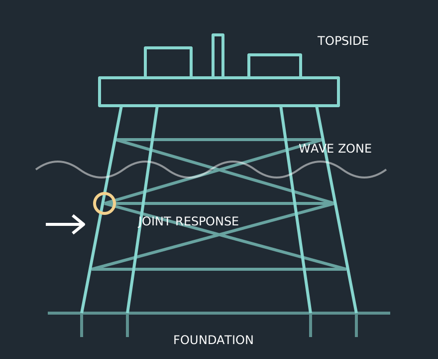
Wave-load calculation starts with a physical model: what moves, what is submerged and how large the structure is relative to the wave field. Jacket braces, large caissons and floating bodies do not automatically use the same loading method. The calculation below explains the workflow and a stationary slender-member illustration; a project design still needs site data, applicable combinations and an agreed acceptance basis.
1. Define the environment and structural geometry
Collect water depth, tidal and surge levels, wave height and period, direction, current profile and the required environmental statistics. Establish member diameters, inclinations, roughness, marine growth and submerged elevations. Design sea states and fatigue exposure serve different purposes and should be documented separately.
Select a wave theory suited to the relative depth and wave steepness. The resulting velocity and acceleration vary with elevation, position and time. Loading every point with a single surface velocity removes the distribution that determines base shear, overturning and local member demand.
2. Select slender-member or diffraction treatment
For a sufficiently slender member, Morison-type loading represents drag and inertia using local fluid kinematics and empirical coefficients. Where the body's dimensions significantly disturb the incident wave field, diffraction and radiation methods may be necessary. Do not decide solely from diameter: consider wavelength, geometry, motion and the applicability limits of the selected formulation.
DNV-RP-C205 addresses assessment and application of environmental loads on marine structures. Its scope includes wind, waves and current; the project must still identify the adopted edition and the associated structural design criteria.
3. Understand the Morison terms
For a stationary circular member in a simplified unidirectional case, force per unit length can be written f(t) = 0.5 ρ C_D D u(t)|u(t)| + ρ C_M (πD²/4) a(t). Here ρ is water density, D the effective diameter, u the local velocity normal to the member and a the corresponding acceleration. C_D and C_M are drag and inertia coefficients chosen for the applicable flow and surface conditions.
For inclined members, use the appropriate normal components. For moving structures, relative kinematics and added-mass treatment require a consistent moving-body formulation. Simply substituting a relative velocity into every term without checking the governing convention can double-count or omit inertia effects.
4. Check a bounded numerical example
Assume a stationary 1.0 m diameter member, water density 1,025 kg/m³, C_D = 1.0, C_M = 2.0, local normal velocity 2.0 m/s and simultaneous acceleration 0.5 m/s². The illustrative drag term is 2,050 N/m; the inertia term is approximately 805 N/m. If their directions agree at that instant, their sum is about 2,855 N/m.
These assumed coefficients are not design recommendations. Peak velocity and peak acceleration do not generally occur at the same instant, so adding their separate maxima is not a valid reconstruction of the peak time history. Integrate the time-consistent distribution along the member rather than multiplying one elevation's value by the whole depth.
5. Transfer loads and verify the structural response
Map distributed forces into the structural model without losing their resultant or moment. Evaluate wave directions and phases, hydrodynamic interference where applicable, and concurrent environmental actions. Check reaction balance, overturning moment and sensitivity to discretisation, coefficients and marine growth.
Deliver the metocean basis, wave model, coefficient rationale, loading diagrams and governing combinations alongside the structural results. If the decision concerns fatigue, retain the stress-range information needed for cycle assessment rather than reporting only maximum member forces.
Frequently Asked Questions
No. Its applicability depends on the relationship between member geometry and the wave field. Large-volume or moving bodies may require a different or coupled treatment.
Technical references & further reading
Practical engineering explainers connecting analysis methods, design inputs and project decisions.
Related articles.
Let's Build Something Great Together.
Partner with Fluxiss for engineering that holds up - under pressure, under load, under scrutiny.