Offshore Jacket Platform Fatigue Analysis: How Wave Loading Creates Hidden Damage
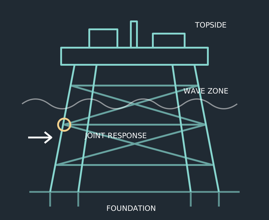
Offshore jacket fatigue analysis asks how repeated loading affects welded details over time. The controlling event may be a large population of ordinary waves rather than one exceptional storm. A low static utilisation therefore does not establish adequate fatigue life. The assessment must connect environmental exposure, structural response, local stress ranges and a fatigue resistance model that suits the detail.
Build the exposure model before calculating damage
Start with the intended assessment period and a directional sea-state scatter description. Establish wave height and period combinations, occurrence probabilities, current assumptions and marine growth. For an existing jacket, separate past exposure from the proposed future period; a new design-life calculation cannot erase the load history already experienced.
Confirm that downtime, operating changes and unusual events are represented consistently. If historical records are incomplete, state the reconstruction method and compare reasonable alternatives. The uncertainty belongs in the decision, not just in a footnote.
Translate waves into structural stress histories
A global model supplies member forces and dynamic response. Check mass, buoyancy treatment, hydrodynamic loading, damping and pile restraint before extracting stresses. A spectral approach can be efficient where its linear assumptions are appropriate; time-domain assessment can accommodate response features that need explicit histories. Select the method from the physics and assessment basis.
At a tubular connection, nominal axial and bending stresses must be converted into the stress definition used by the fatigue method. Chord flexibility, brace angle and wall thickness matter. DNV's tubular-joint workflow explicitly connects beam models with local finite element treatment; this is a reminder to preserve both the global load path and the local detail.
Match stress definition to the fatigue curve
Nominal stress, structural hot-spot stress and local notch stress are different quantities. Applying a curve calibrated for one quantity to another can distort the predicted life. Record the curve basis, environment, thickness correction and weld condition, together with the method used to extract the stress range.
Do not treat a singular nodal peak at an ideal sharp weld as a directly usable fatigue stress. Refine the model and apply the chosen method's stress extraction rules. A mesh-sensitive peak and a converged structural stress require different interpretations.
Calculate and review cumulative damage
For a simple linear damage illustration, D = sum(nᵢ/Nᵢ): nᵢ is the applied cycle count in a stress-range bin and Nᵢ is the corresponding fatigue resistance in cycles. This is a bookkeeping model, not a standalone acceptance criterion. Applicable design fatigue factors, accessibility, consequence and inspection arrangements affect the assessment basis.
Review damage contributions by sea state, direction and stress range. A result dominated by one unexplained bin may reveal a units, probability or response-processing error. Compare neighbouring joints and check that symmetrical geometry behaves plausibly under comparable loading.
Connect calculated life to inspection and intervention
Report critical locations, stress extraction positions, fatigue assumptions and sensitivity to uncertain inputs. Inspection planning should target details that control the assessment while acknowledging detectability and access. DNV-RP-C203 provides methods for offshore steel fatigue assessment; use the project-adopted provisions rather than a generic software default.
Where a crack already exists, an uncracked-detail life estimate alone is insufficient. Characterise the defect and determine whether fracture-mechanics assessment, repair or operating restrictions are needed within the integrity management process.
Frequently Asked Questions
Yes. Repeated stress ranges can initiate and grow cracks at welded details without gross yielding of the member.
Technical references & further reading
Practical engineering explainers connecting analysis methods, design inputs and project decisions.
Related articles.
Let's Build Something Great Together.
Partner with Fluxiss for engineering that holds up - under pressure, under load, under scrutiny.