Why Offshore Jacket Structures Fail: 7 Critical Design and Analysis Problems
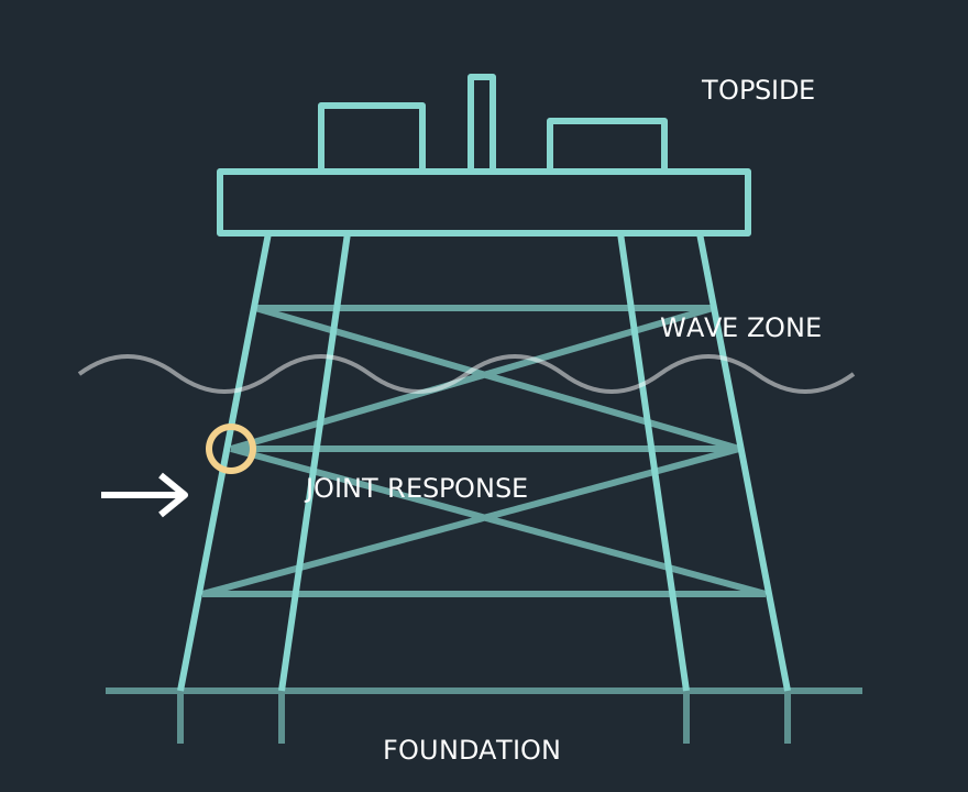
An offshore jacket carries topside loads into the seabed while resisting environmental actions throughout its service life. A satisfactory member stress check is only one part of that task. Failure can develop where loads, connections, deterioration or foundation behaviour differ from the assumptions in the model. The following seven problems provide a practical starting point for design reviews and existing-platform assessments; they are not a statistical ranking of failure causes.
1. Environmental loads do not represent the site
A single wave height does not define a loading environment. Water depth, period, direction, current profile, water level and marine growth influence the load distribution. Examine the environmental basis alongside the model: a larger drag diameter or different wave direction can move the governing load away from the apparently critical member.
2. Repeated loading is treated as a strength problem
A structure can remain below its static strength limit while accumulating fatigue damage. Frequent sea states may contribute substantially through their cycle counts. Keep extreme-event checks and fatigue checks separate, and document how the operating life and future exposure are represented.
3. Tubular joints are reduced to beam intersections
The chord wall deforms locally where braces meet it. Nominal beam stresses do not directly describe this behaviour. Check joint geometry, overlapping braces, eccentricity and the applicability of stress concentration factors. Use a suitable local model when the joint lies outside the selected method's assumptions.
4. Corrosion is represented by an average thickness
Scattered measurements can hide a locally thinned brace, splash-zone band or damaged connection. Associate thickness readings with actual members and elevations. Evaluate the shape and extent of metal loss, then check its influence on section resistance, local buckling and joint behaviour rather than applying one platform-wide percentage.
5. Foundation stiffness is assumed rather than examined
An ideal fixed base may misrepresent pile-head movement, load sharing and natural periods. Use the geotechnical basis appropriate to the assessment, including scour and cyclic effects where relevant. Compare plausible stiffness bounds to identify conclusions that depend on uncertain soil information.
6. Accidental damage and temporary states are omitted
A vessel strike can dent a brace and interrupt a load path even when the undamaged platform satisfies environmental combinations. Lifting, transport, installation and repair states also introduce different restraints. Define the required accidental scenarios and inspect the damaged geometry before predicting residual capacity.
7. Modifications never reach the analysis model
Added equipment changes weight, centre of gravity and sometimes wind area. Removed braces, replacement supports and new penetrations can change stiffness or connectivity. Reconcile the analysis model with as-built drawings, inspection findings and the latest weight register before accepting a utilisation table.
Turn findings into an assessment plan
Begin with a discrepancy register: what is known, what is assumed and which missing input could change the outcome? HSE's structural integrity guidance describes a lifecycle involving inspection, analysis and repair. Use that principle to connect each assessment finding to a specific inspection, model update or repair decision.
A useful deliverable identifies the governing member and joint, load case, condition assumption and acceptance basis. It should also distinguish verified capacity from conditional conclusions. Send Fluxiss the structural drawings, inspection history, metocean basis and proposed operating changes to define an integrated offshore assessment scope.
Frequently Asked Questions
No. Global response must be complemented by applicable joint, fatigue, foundation, deterioration and accidental-condition checks.
Technical references & further reading
Practical engineering explainers connecting analysis methods, design inputs and project decisions.
Related articles.
Let's Build Something Great Together.
Partner with Fluxiss for engineering that holds up - under pressure, under load, under scrutiny.