When Should You Use FEA for Pressure Vessel Design?
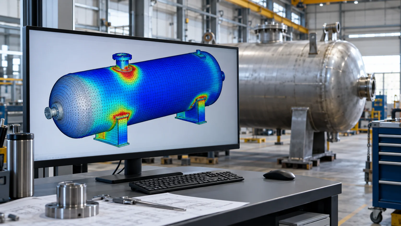
Finite element analysis is useful when a pressure-vessel decision depends on behaviour that a suitable design-by-rule calculation does not resolve. It is also useful for understanding margins and comparing details. The starting question is not whether the geometry can be meshed, but which failure modes need assessment and how the selected analysis method fits the governing construction or in-service code.
Recognise the situations that may need detailed analysis
Closely spaced openings, unusual transitions, substantial external nozzle loads and complex support regions can require more detailed evaluation. Thermal gradients and cyclic duty may introduce stress distributions that a pressure-thickness check does not describe. External pressure or compressive loading may make stability the governing issue.
First review the applicability of available closed-form methods. A valid design-by-rule method can be efficient and reviewable. FEA should answer a defined gap or verification need, not merely duplicate an existing calculation with a more colourful result.
Choose the acceptance route before building the model
Define the governing code and permitted design-by-analysis route, then map each required failure check to the analysis and output it needs. Plastic collapse, local failure, buckling and cyclic effects are distinct concerns. A single elastic equivalent-stress maximum does not establish all of them.
ASME's Section VIII guidebook covers design-by-analysis alongside other vessel design topics. Detailed use requires the adopted rules, their applicability and competent interpretation; software availability alone does not authorise substitution of one code route for another.
Model the vessel and its interfaces consistently
Use the geometry and thickness basis required for the assessment, including corrosion treatment. Include pressure end effects, support stiffness, nozzle loading and temperature distributions where applicable. Shell, solid and mixed models can each be suitable if their interfaces and extraction methods represent the intended behaviour.
A local nozzle model needs enough surrounding shell to avoid boundary distortion. If a global model supplies displacements or loads, confirm compatibility and check that local refinement does not materially change the global stiffness assumption. Carry actual load combinations through the transfer.
Verify the result and interpret stress correctly
Check reaction balance, simple reference solutions and mesh sensitivity before assessing margins. For elastic stress-classification methods, define the stress classification lines and justify membrane, bending and other stress treatment. A raw peak at a sharp idealised corner may be singular and unsuitable for direct acceptance comparison.
Where nonlinear analysis is required, document material data, increments, contact behaviour and convergence. An eigenvalue buckling factor is an idealised screening result; imperfections and nonlinear effects may be needed for the applicable capacity assessment.
Issue an assessment that a reviewer can follow
Provide the code basis, model geometry, materials, load table, boundary assumptions, mesh study, failure-mode checks and conclusion. Include sufficient plots and numerical tables to trace the controlling result. Record limitations such as uncertain support stiffness or unavailable temperature histories.
Fluxiss can scope detailed vessel FEA alongside pressure calculations and nozzle-load review. Supplying fabrication drawings, material specifications, design conditions, duty cycles and equipment-interface loads helps establish whether detailed analysis is necessary and which outputs should control the decision.
Frequently Asked Questions
No. It must fit an applicable assessment route and be accompanied by the other required design, fabrication, inspection and documentation provisions.
Technical references & further reading
Practical engineering explainers connecting analysis methods, design inputs and project decisions.
Related articles.
Let's Build Something Great Together.
Partner with Fluxiss for engineering that holds up - under pressure, under load, under scrutiny.