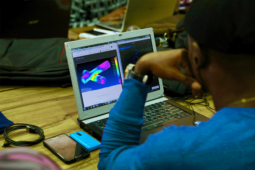
A converged solver has solved the model it was given. It has not established that the model represents the real assembly or that the plotted stress is the right acceptance quantity. Before changing a design because of an FEA contour, review these ten sources of error. Each check should answer a physical question and leave evidence another engineer can inspect.
1. Units and material data are inconsistent
Audit geometry scale, density, elastic modulus and every applied load in one coherent unit system. Then confirm temperature-dependent properties where they matter. A model can be numerically stable while its mass or stiffness is wrong by several orders of magnitude.
2. Supports are more rigid than the actual installation
A fully fixed face suppresses motion that a bolt group, foundation or neighbouring component may permit. Start with the physical restraint mechanism. Compare plausible interface stiffnesses and check whether the acceptance conclusion depends on an unrealistically rigid support.
3. Loads do not follow the physical load path
A concentrated force, distributed pressure and remote load are not interchangeable near the introduction region. Include eccentricity, pressure end effects where applicable, preload and the operating combinations required by the design basis. Verify resultant forces and moments independently.
4. Contacts conceal separation or slip
Bonded contact can create stiffness and transfer tension across an interface that can actually open. Check gaps, friction, contact normals and preload sequence. Inspect contact status and pressure during the solution, rather than judging the setup only from the undeformed assembly.
5. The element formulation is unsuitable
A thin bending-dominated feature needs a formulation and discretisation that can represent bending. Check shell offsets, beam orientations, integration settings and solid-element quality. Element count is not a substitute for suitable elements in the regions that control response.
6. One mesh is mistaken for convergence
Refine the decision-relevant output across a consistent sequence of meshes. Displacement may stabilise while a local stress remains unresolved. Track the same location and stress definition, and keep geometry and loads unchanged so mesh effects can be isolated.
7. A singular peak is reported as a usable stress
Sharp re-entrant corners and ideal point constraints can produce increasing peak stress as the mesh is refined. Investigate the cause and apply a physically justified geometry or an appropriate structural-stress method. Neither accepting nor deleting the largest value without explanation is a review method.
8. Nonlinear behaviour is omitted
Large deflection, material yielding or changing contact can invalidate a linear response assumption. Compare deformation with the geometry and inspect whether the load path changes. A nonlinear solver also needs suitable material data, increments and convergence checks; switching it on is not validation.
9. The wrong output is compared with the limit
Maximum von Mises stress alone does not assess every failure mode. Fatigue needs an appropriate stress range; buckling needs stability assessment; brittle failure may need a different criterion. Match each extracted quantity to its failure mode and governing acceptance method.
10. No independent evidence supports the result
Check reaction balance, deformation shape and an order-of-magnitude calculation. Use benchmarks or test measurements appropriate to the intended use. ASME's verification and validation publications distinguish computational checks from evidence that the model represents reality; both matter to confidence in a design decision.
What a reviewable FEA package contains
Keep a model register, load-case table, material sources, mesh study, interface assumptions and acceptance mapping. Identify unresolved sensitivities and state how they affect the conclusion. A second engineer should be able to follow the result from an input drawing to the final recommendation without reverse-engineering a screenshot.
Frequently Asked Questions
No. It establishes a numerical solution under the chosen settings, not that geometry, physics, inputs or acceptance criteria are correct.
Technical references & further reading
Practical engineering explainers connecting analysis methods, design inputs and project decisions.
Related articles.


Let's Build Something Great Together.
Partner with Fluxiss for engineering that holds up - under pressure, under load, under scrutiny.