Fluxiss Pressure Vessel Design Now Covers Four Defined Scopes, From ASME Section VIII Calculations to API 650 Tanks and FEA Verification
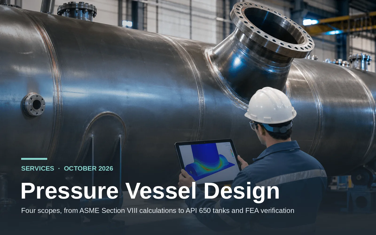
Fluxiss has set out its pressure vessel design service on fluxiss.com as four defined scopes, each with its own place on the service page, so plant owners, fabricators and EPC contractors can match a vessel or tank question to the right level of analysis before a proposal is written. The service is referenced to ASME Section VIII Division 1 and Division 2, EN 13445 and API 650, and is delivered for oil and gas, petrochemical, chemical processing, power generation and renewable energy projects in the USA, UK and UAE.
The first scope, vessel design and calculation, is the design-by-rule core of the work: shell, head, nozzle and reinforcement calculations to ASME Section VIII, starting from the user design specification and the material allowable stresses, and ending with the minimum required thickness, the maximum allowable working pressure and the corrosion allowance written into the calculation package. External pressure cases for vacuum and subsea conditions are checked under the same route. The Design and Calculation page explains how the design-by-rule calculation is built up and where Division 2 design by analysis takes over. The second scope, storage tank design, covers API 650 atmospheric tanks with the wind, seismic and annular plate checks that tank work needs and that a vessel code does not provide.
“Owners, fabricators and EPC contractors can now scope vessel and tank work on fluxiss.com against four defined scopes - vessel design and calculation, storage tank design, nozzle and saddle analysis and FEA verification - with the codes, tools, deliverables and turnaround set out on the Pressure Vessel Design page.”
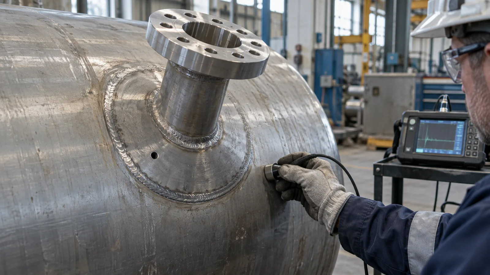
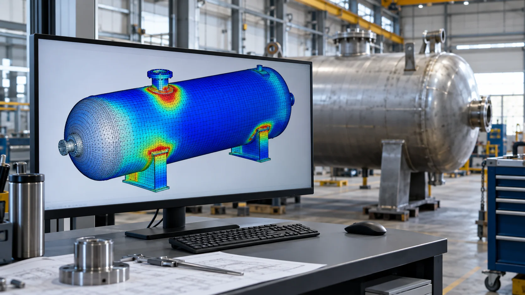
The third scope, nozzle and saddle analysis, deals with the places where piping loads and support reactions meet the shell. Local stresses at nozzles and saddles are evaluated to WRC 107 and WRC 537, with FEA used where the geometry or the loads fall outside the bulletin limits. The nozzle loads themselves usually arrive from a pipe stress analysis of the connected lines, which follows ASME B31.3 while the vessel stays under Section VIII. The fourth scope, FEA verification, applies linear and non-linear finite element analysis to the cases that closed-form rules do not resolve: closely spaced openings, unusual transitions, heavy support regions, thermal gradients and cyclic duty. The Safety and Compliance page sits alongside the four scopes and covers non-destructive testing procedures, relief valve sizing and overpressure protection to API RP 520 and 521, and hydrostatic testing.
Every engagement produces the same set of documents listed on the service page: a design calculation package as a PDF, the PV Elite or COMPRESS model, an FEA report where the scope calls for one, a general arrangement drawing, a material and UDR summary and a compliance summary. Models are built in PV Elite and COMPRESS, with ANSYS used for the FEA cases and NozzlePRO for local stress and flange evaluation, and the typical turnaround is 7 to 14 business days depending on scope.
The split reflects how vessel questions arrive in practice. A horizontal separator on two saddles with standard nozzles is a design-by-rule job with WRC checks at the connections. A tank farm is an API 650 problem with its own wind and seismic checks rather than a Section VIII one. A reactor with closely spaced nozzles, a vessel in cyclic service or a column with an unusual skirt-to-shell transition is a Division 2 design-by-analysis case, and the FEA should be scoped and budgeted from the start. Setting the scope correctly early avoids paying for design by analysis on a vessel that the Division 1 rules cover, and avoids finding out at third-party review that a rule-based calculation was not enough for the geometry in hand.
Supporting material sits alongside the service pages. The pressure vessel topic hub collects practical guides on choosing between Division 1 and Division 2 design methods, how MAWP is calculated, nozzle reinforcement calculation problems, when FEA is needed for a vessel, external pressure and vacuum design, skirt, saddle and leg supports, fatigue analysis under cyclic loading, corrosion allowance in thickness calculations, the hydrotest and inspection checklist and why vessel calculations fail at third-party review. For engineers checking their own PV Elite or COMPRESS output, the products store carries the Pressure Vessel Design Master Workbook. Teams who would like a scope review can start from the Pressure Vessel Design page, write to inquiries@fluxiss.com or book a meeting with the team.
Fluxiss Team contributes services insights to the Fluxiss content library.
Related articles.

Let's Build Something Great Together.
Partner with Fluxiss for engineering that holds up - under pressure, under load, under scrutiny.