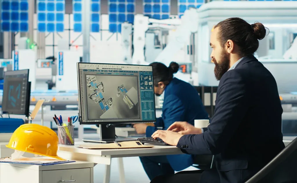
This service spotlight explains how the Fluxiss Computer Aided Design service turns sketches, specifications and existing parts into CAD that engineers can edit and workshops can build from. Software alone does not deliver clarity; process does. A model with broken references or a drawing with missing tolerances stalls a project just as surely as having no model at all. Fluxiss supports product, fabrication and engineering teams across the USA, UK, Europe and the UAE, and the work follows three threads: 3D parametric modeling, 2D technical drafting and reverse engineering.
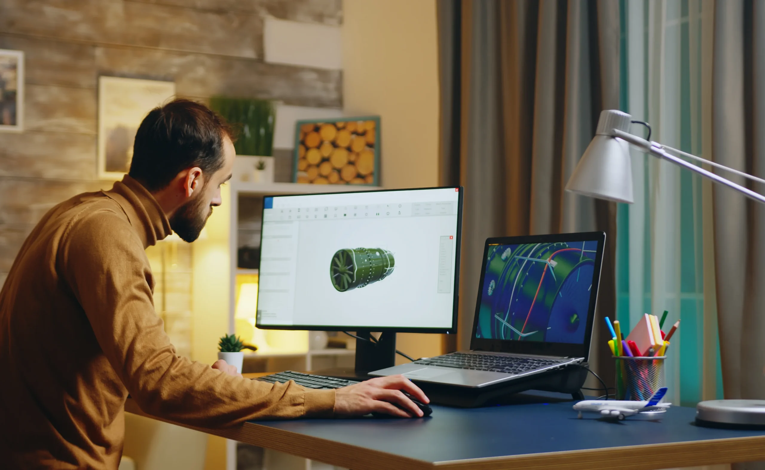
3D Parametric Modeling is the foundation. Fluxiss builds feature-based parts and full assemblies driven by dimensions and design intent, so changing one key value updates the whole model instead of forcing a rebuild. Solid models behave like real parts, with mass properties and fits that can be checked; surface modeling handles consumer-product and aerodynamic shapes where smooth, continuous geometry matters; and sheet-metal design delivers flat patterns, bend tables and thickness rules so parts unfold cleanly at the press brake.
“How the Fluxiss Computer Aided Design service produces edit-ready, manufacturing-ready CAD: parametric solid, surface and sheet-metal models, fabrication and assembly drawings with GD&T to ASME Y14.5 or BS 8888, and reverse engineering when only a part exists.”
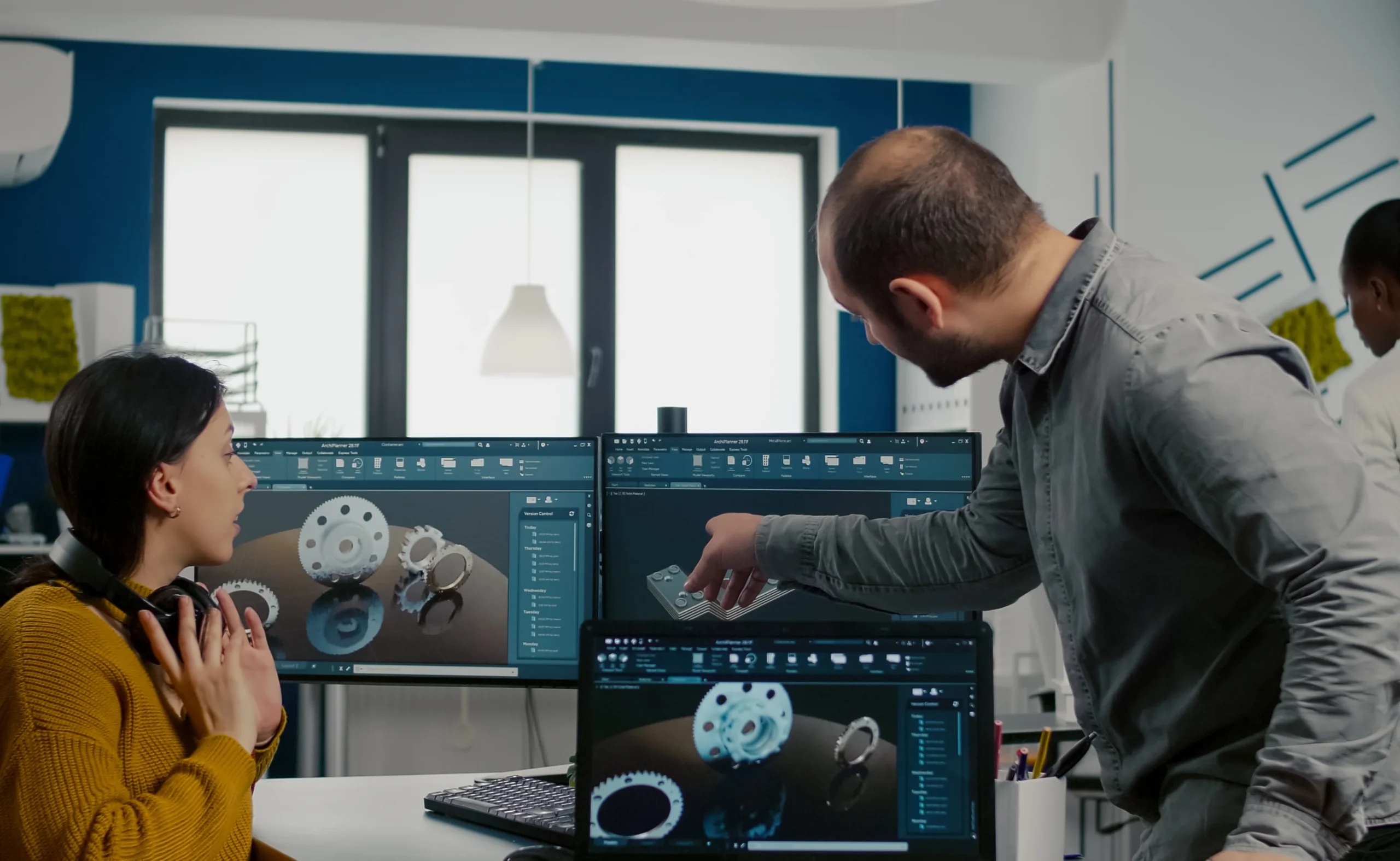
2D Technical Drafting is the part that still decides everything on the shop floor. Machinists and fabricators work from drawings, so Fluxiss prepares fabrication, assembly and detail drawings with clear views, sections, bills of materials and revision blocks. GD&T is applied deliberately: datums, feature control frames and tolerances chosen around how the part is made and inspected, to ASME Y14.5 for US clients or BS 8888 and ISO conventions for UK and European teams. Wrong tolerances make wrong parts, and this step is where that risk is removed.
Reverse Engineering covers the cases where no usable CAD exists. Scan data from a worn or obsolete part is converted into a clean, parametric model, and faded legacy blueprints are redrawn into modern files, so components can be repaired, reproduced or redesigned without guesswork. The reverse-engineering spotlight describes that workflow from point cloud to production-ready CAD in detail.
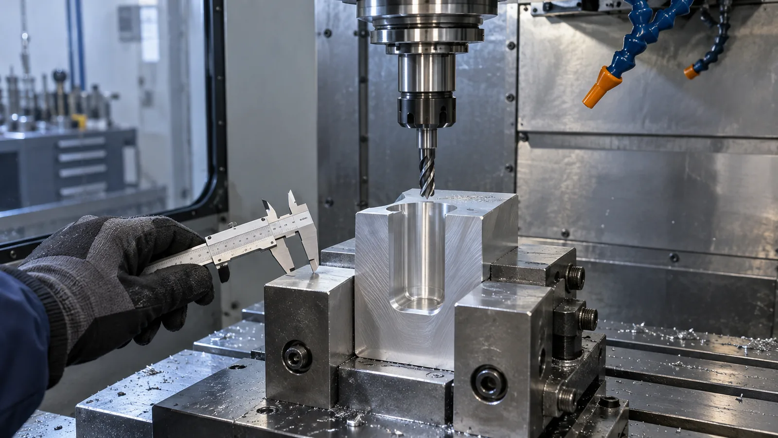
CAD is the starting point for most other Fluxiss services. Computer Aided Manufacturing takes the approved model into toolpaths, fixtures and prototypes, and Finite Element Analysis uses the same geometry to check stress, vibration and fatigue before release. Native files are delivered in SolidWorks, Inventor, Creo, NX or Fusion 360 as the client requires, with STEP, IGES, DWG and PDF exports for suppliers. Our guides to what computer aided design and drafting is, what a parametric 3D model is, why CAD designs are hard to manufacture and the difference between CAD and CAM, together with the CAM spotlight, show how the pieces fit.
A useful CAD enquiry includes the sketches, existing drawings, scan data or sample part, the CAD platform and file formats the team uses, the drafting standard (ASME or BS 8888/ISO), the manufacturing process, critical fits and tolerances, and how many parts or assembly levels are involved. Teams can contact Fluxiss with that information or schedule a technical meeting to agree the scope, modelling approach and drawing deliverables before work begins.
Fluxiss Team contributes services insights to the Fluxiss content library.
Let's Build Something Great Together.
Partner with Fluxiss for engineering that holds up - under pressure, under load, under scrutiny.