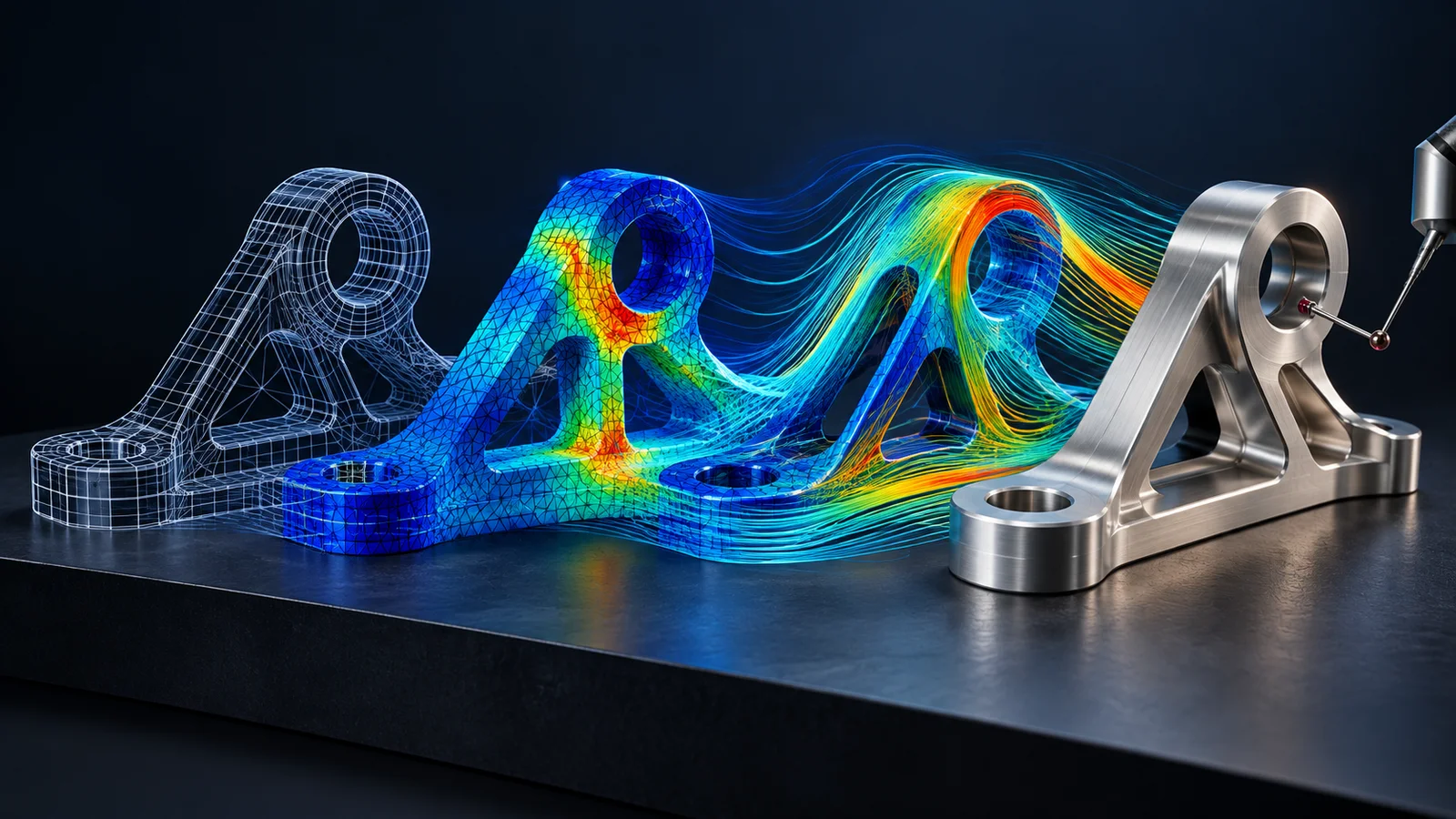
This service spotlight follows the Fluxiss Computer Aided Engineering service from the first digital model to analysis evidence and production-ready information. The published scope brings CAD, finite-element analysis, computational fluid dynamics and manufacturing support under one workflow. That connection is useful when geometry changes during simulation, when results affect material or feature choices, or when a design must move into drawings and machining without losing the assumptions behind the engineering decision.
Geometry is the common reference. Computer Aided Design can establish the controlled assembly, interfaces and drawing definition, while 3D Parametric Modeling allows dimensions and features to be updated without rebuilding the model from the beginning. For a legacy or physical component, Reverse Engineering can reconstruct an as-built model from available measurements or scan data. Before analysis starts, the team should agree which details control the physics, which can be simplified and which interfaces must remain unchanged for fit or manufacturing.
“Explore how Fluxiss connects CAD geometry, FEA, CFD, verification and manufacturing support in one traceable computer-aided engineering workflow.”
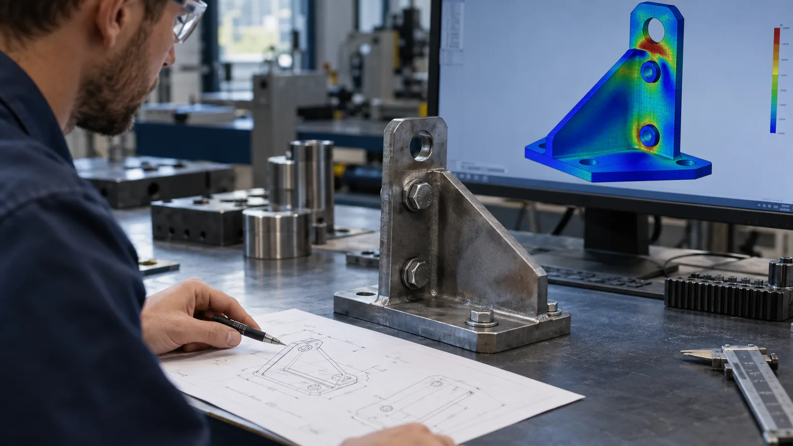
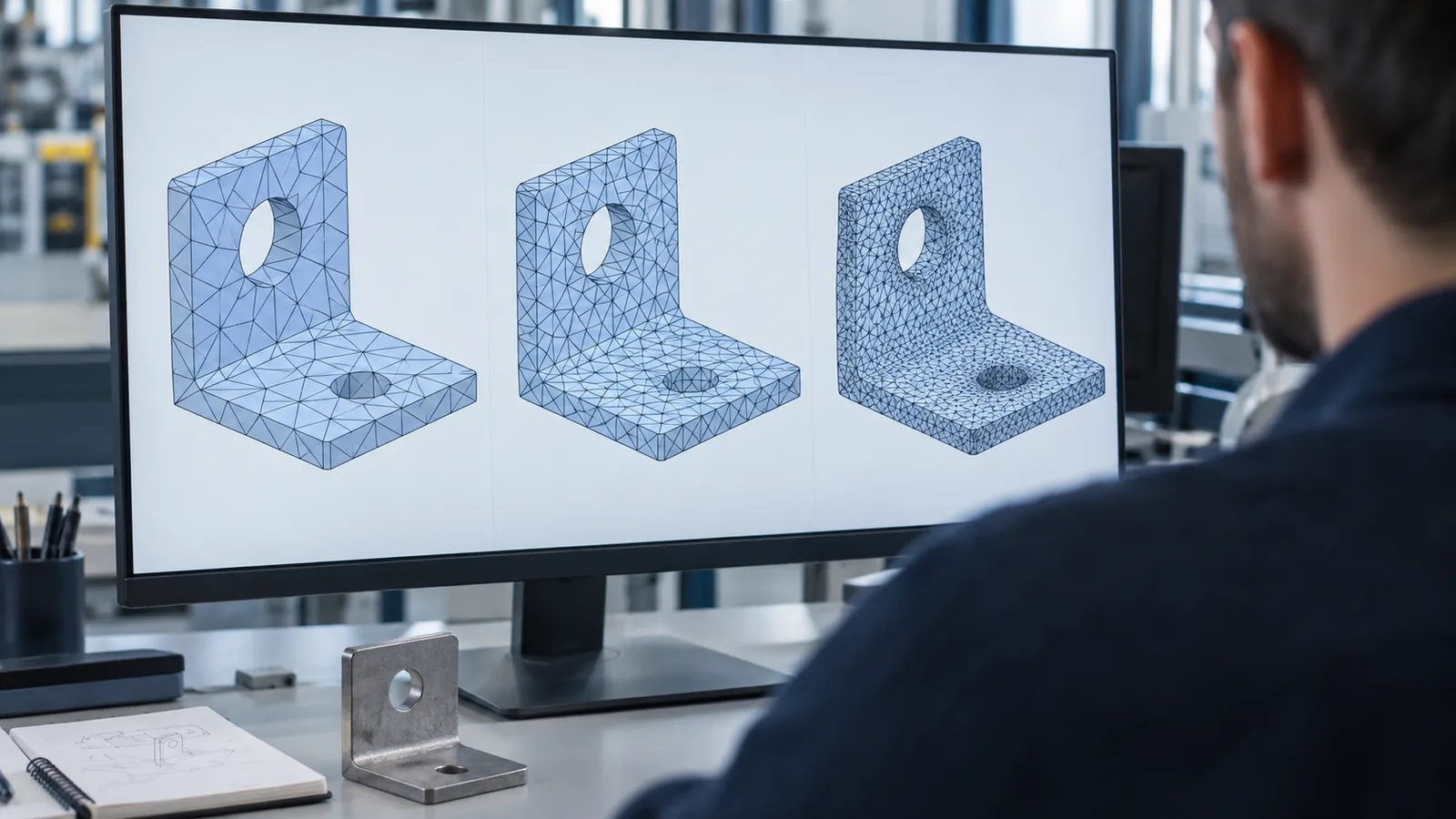
Finite Element Analysis provides the structural branch of the workflow. Static Analysis can address loads and restraints that do not require an explicitly time-varying solution; Dynamic and Time-Dependent Analysis applies where inertia, impact, transient response or changing excitation matters; Thermal and Fatigue Analysis connects temperature fields and load cycles to stress and life questions. The selected method should follow the decision being made. Our guide to why FEA results are wrong covers common modelling errors, and the article on mesh convergence in FEA explains how refinement evidence supports a result rather than simply producing a more detailed image.
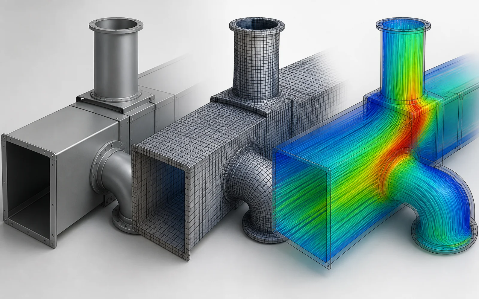
Computational Fluid Dynamics addresses flow, pressure, heat transfer, ventilation, aerodynamics and related transport behaviour. A credible model needs defined boundaries, material properties, turbulence treatment where applicable, monitored quantities and a verification plan. The guide to how CFD works explains the sequence from geometry and meshing to solution and interpretation, while our CFD mesh independence article focuses on demonstrating that the reported engineering quantity is not controlled by an arbitrary cell size. Simulation outputs should be reported against the project question and available validation evidence, not judged only by visual contours.
When the design is ready to move toward production, Computer Aided Manufacturing can connect approved geometry to tooling, fixtures and process planning. CNC Programming translates the manufacturing strategy into reviewed toolpaths and setup information, while Rapid Prototyping can support fit checks or early design verification before final production. Fluxiss lists native model and case files, FEA or CFD reports, mesh studies, fabrication drawings, bills of material, CNC programs and setup information among the available deliverables. The project scope should define file formats, revision ownership and whether manufacture or testing is included.
To scope a CAE project, contact Fluxiss with the engineering question, current geometry, materials, operating and load cases, boundary conditions, available test data, acceptance criteria and required deliverables. Clients can also schedule a technical meeting to decide whether the next step is CAD preparation, FEA, CFD, manufacturing support or a connected package. Software, standards, verification activities and programme are confirmed for the specific project rather than assumed from a general service page.
Fluxiss Team contributes services insights to the Fluxiss content library.
Let's Build Something Great Together.
Partner with Fluxiss for engineering that holds up - under pressure, under load, under scrutiny.